Extreme ultra violet light source apparatus

a technology of ultra violet light source and ultra violet light, which is applied in the field oflp, can solve the problems of further decrease in damage to the window, and achieve the effect of preventing the window of the euv light generation chamber and/or the laser beam collecting optics from deteriorating and preventing the efficiency of euv light generation from decreasing

Active Publication Date: 2010-03-23
GIGAPHOTON
View PDF16 Cites 4 Cited by
  • Summary
  • Abstract
  • Description
  • Claims
  • Application Information

AI Technical Summary

Benefits of technology

[0026]The present invention has been developed with these problems being taken into account. An object of the present invention is to provide an extreme ultra violet light source apparatus capable of preventing the reduction in the efficiency of generation of the EUV light due to the deterioration of the window of the EUV light generation chamber.
[0028]According to the present invention, it is possible to prevent the window of the EUV light generation chamber and / or the laser beam collecting optics from deteriorating and to prevent the efficiency of generation of EUV light from decreasing.

Problems solved by technology

Such a decrease in the ability to collect light causes a further decrease in the efficiency of generation of the EUV light 121.
Furthermore, if the distortion of the window 106 becomes larger, it may eventually lead to damage of the window 106.

Method used


Image

  • Extreme ultra violet light source apparatus
  • Extreme ultra violet light source apparatus
  • Extreme ultra violet light source apparatus

Examples


first embodiment

[0046]Next, an EUV light source apparatus according to the present invention will be described.

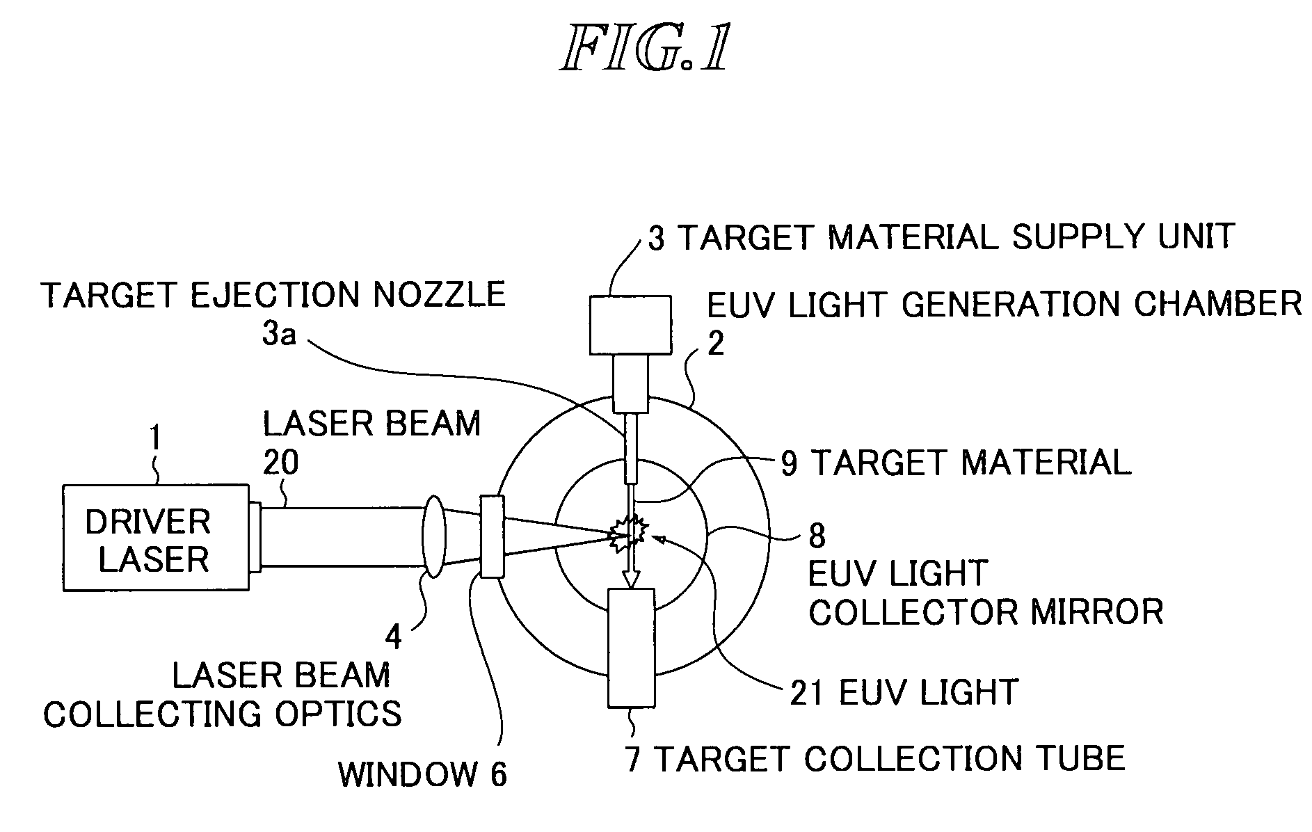
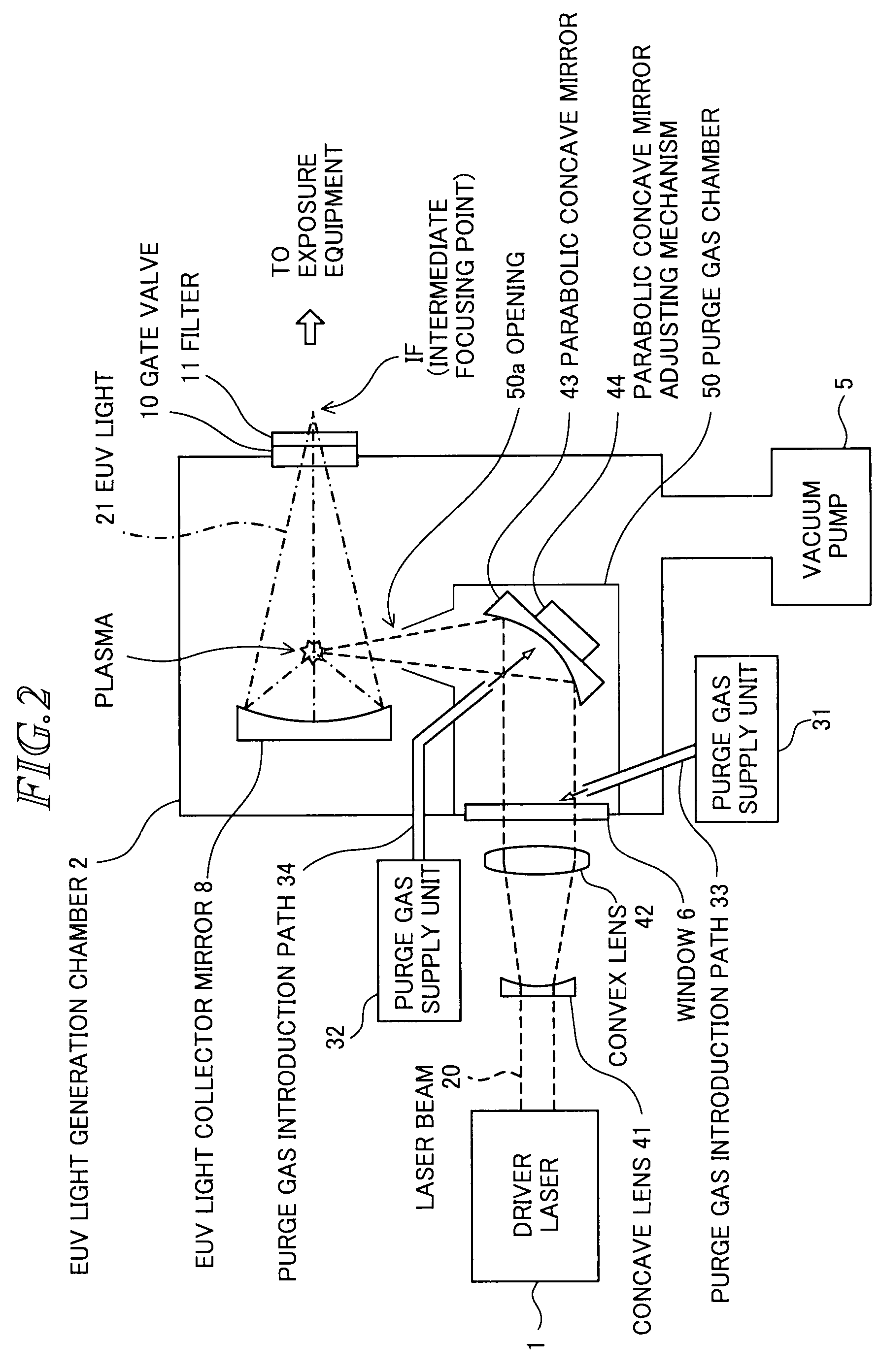
[0047]FIG. 2 is a schematic diagram showing the EUV light source apparatus according to the present embodiment. In FIG. 2, the target material supply unit 3 and the target material collection tube 7 (refer to FIG. 1) are not shown schematically, and it is assumed that the target material is ejected in the vertical direction to the drawing.

[0048]As shown in FIG. 2, a laser beam 20 emitted from the driver laser 1 in the rightward direction in the drawing is enlarged by a concave lens 41, collimated by a convex lens 42, transmitted through the window 6, and input into the EUV light generation chamber 2. As the material of the concave lens 41, the convex lens 42, and the window 6, those which absorb the laser beam 20 little, such as synthetic quartz, CaF2, MgF2, etc., are preferable. When an infrared laser such as CO2 laser, etc. is used as the driver laser 1, ZnSe, GaAs, Ge, Si, etc. are suit...

second embodiment

[0064]Next, an EUV light source apparatus will be described.

[0065]FIGS. 5 and 6 are schematic diagrams showing the EUV light source apparatus according to the present embodiment. In FIGS. 5 and 6, the target material supply unit 3 and the target material collection tube 7 (refer to FIG. 1) are not shown schematically, and it is assumed that the target material is ejected vertically to the drawing.

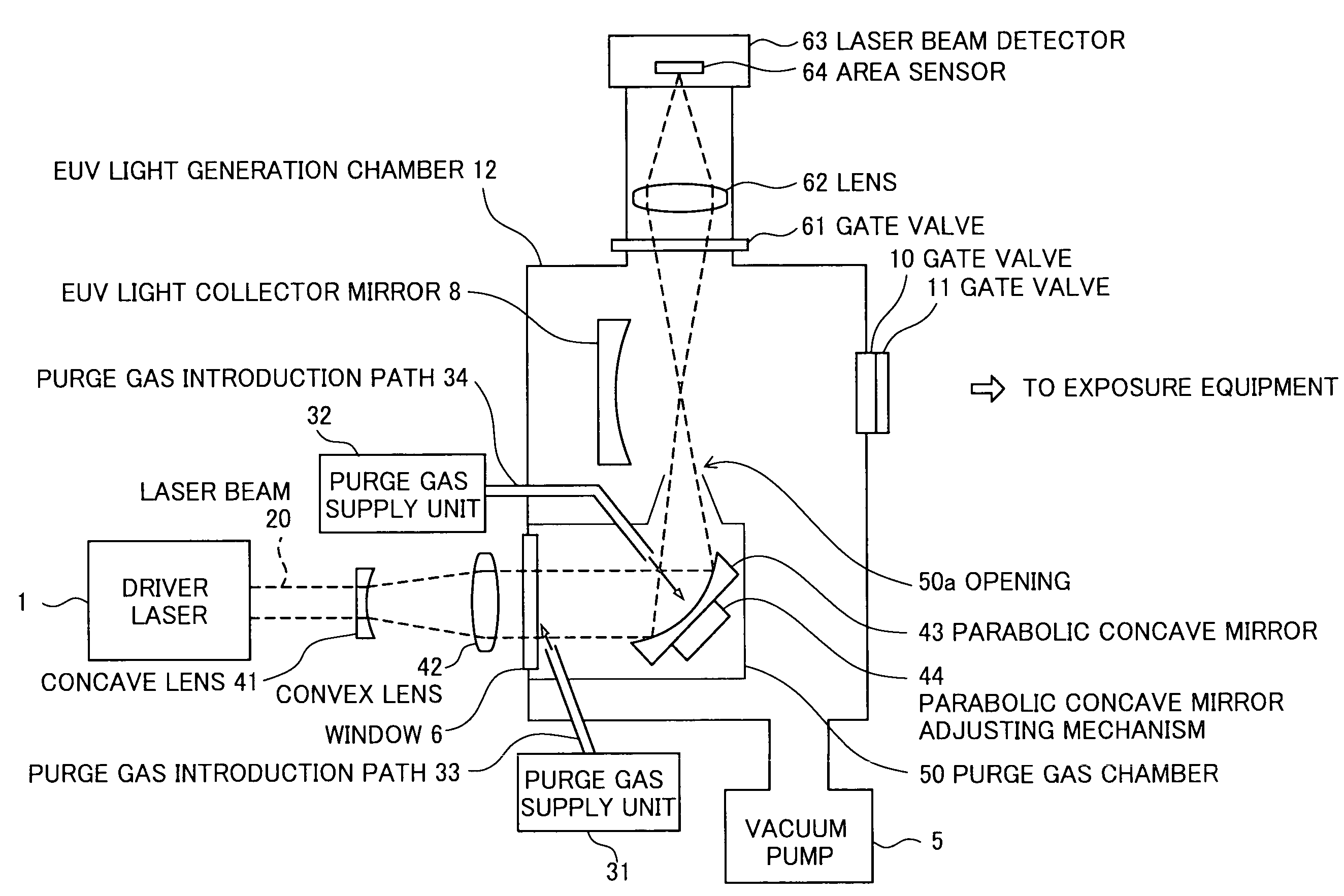
[0066]As shown in FIGS. 5 and 6, the EUV light source apparatus further includes a gate valve 61, a lens 62, and a laser beam detector 63, in addition to the EUV light source apparatus according to the first embodiment described above. The laser beam detector 63 includes an area sensor 64.

[0067]FIG. 5 is a schematic diagram showing the EUV light source apparatus according to the present embodiment when emitting the EUV light, and FIG. 6 is a schematic diagram showing the EUV light source apparatus according to the present embodiment when the parabolic concave mirror is aligned.

[0068]As sho...

third embodiment

[0070]Next, an EUV light source apparatus according to the present invention will be described.

[0071]FIG. 7 is a schematic diagram showing the EUV light source apparatus according to the present embodiment. In FIG. 7, the target material supply unit 3 and the target material collection tube 7 (refer to FIG. 1) are not shown schematically, and it is assumed that the target material is ejected vertically to the drawing.

[0072]As shown in FIG. 7, the laser beam 20 emitted upward in the drawing from the driver laser 1 is enlarged by the concave lens 45, collimated by a convex lens 46, transmitted through the window 6, and input into an EUV light generation chamber 13.

[0073]In the EUV light generation chamber 13, a spherical concave mirror 47 and a spherical concave mirror adjusting mechanism 48 that adjusts the position and angle (tilt angle) of the spherical concave mirror 47 are arranged.

[0074]The laser beam 20 having been transmitted through the window 6 and input into the EUV light g...


PUM


Abstract

An EUV light source apparatus capable of preventing the efficiency of generation of EUV light from decreasing due to deterioration of a window of an EUV light generation chamber. The EUV light source apparatus includes an EUV light generation chamber provided with a window, a driver laser which generates a laser beam, a concave lens which enlarges the laser beam, a convex lens which collimates the enlarged laser beam, a parabolic concave mirror which is arranged in the EUV light generation chamber and reflects the collimated laser beam to collect the laser beam to a target material, a parabolic concave mirror adjusting mechanism which adjusts position and angle of the parabolic concave mirror, an EUV light collector mirror which collects EUV light, and a purge gas supply unit which supplies a purge gas for protecting the window and the parabolic concave mirror.

Description

BACKGROUND OF THE INVENTION[0001]1. Field of the Invention[0002]The present invention relates to an LPP (laser produced plasma) type EUV (extreme ultra violet) light source apparatus that generates extreme ultra violet light to be used for exposing a semiconductor wafer or the like.[0003]2. Description of a Related Art[0004]Recently, as semiconductor processes become finer, photolithography has been making rapid progress toward a higher resolution, and for the next generation, micro-fabrication of 100 nm to 700 nm, and further, micro-fabrication of 50 nm or less is being required. Accordingly, in order to meet the requirement of micro-fabrication of 50 nm or less, for example, exposure equipment is expected to be developed by combining an EUV light source generating extreme ultra violet light with a wavelength of approximately 13 nm and reduced projection reflective optics.[0005]The EUV light sources include three kinds, namely, an LPP (laser produced plasma) light source using plas...

Claims


Application Information

Patent Timeline
Patent Type & Authority Patents(United States)
IPC IPC(8): H05G2/00A61N5/06G01J3/10G21G4/00
CPCH05G2/001
Inventor MORIYA, MASATOABE, TAMOTSUSUGANUMA, TAKASHISOMEYA, HIROSHIYABU, TAKAYUKISUMITANI, AKIRA
Owner GIGAPHOTON
Why Eureka
Try Eureka