Electricity generation in a turbomachine

a technology of electric power generation and turbomachine, which is applied in the direction of electric generator control, machines/engines, mechanical apparatuses, etc., can solve the problem of not being suited to use on an aeronautical turbomachin

Active Publication Date: 2010-03-30
SN DETUDE & DE CONSTR DE MOTEURS DAVIATION S N E C M A
View PDF10 Cites 20 Cited by
  • Summary
  • Abstract
  • Description
  • Claims
  • Application Information

AI Technical Summary

Benefits of technology

[0008]The Stirling cycle thermal engine, commonly called “Stirling engine” or hot air engine, makes it possible to exploit the temperature difference between the primary flow of exhaust gas and the secondary flow of cold air to generate mechanical energy, which can be converted into electrical energy. This type of engine is characterized by a very good efficiency which can reach 40% as a theoretical maximum, with very good reliability and long life.
[0012]This regenerator is an exchanger that forms a thermal accumulator which makes it possible to increase the efficiency of the Stirling engine.
[0016]This arrangement makes it possible to reduce the bulk of the device while providing a space for the regenerator.
[0019]Advantageously, the Stirling engine is sealed and filled with a pressurized inert gas such as helium. As a variant, it can comprise a pressurized gas inlet, for example into the working chamber or into one of the exchangers, so as to increase the pressure of the working fluid and, consequently, the efficiency of the Stirling engine.
[0022]The invention thus makes it possible to generate electricity, to provide the electrical power supply for an airplane for example, and without having to tap useful mechanical energy in the turbomachine.

Problems solved by technology

Already known is a method of driving an electrical generator by means of an engine operating according to a Stirling cycle, but such a generator is a heavy machine designed to operate in co-generation mode with heating means for residential or office buildings as described, for example, in the document GB-A-2 391 299, and is not suited to use on an aeronautical turbomachine.

Method used


Image

  • Electricity generation in a turbomachine
  • Electricity generation in a turbomachine
  • Electricity generation in a turbomachine

Examples


Embodiment Construction

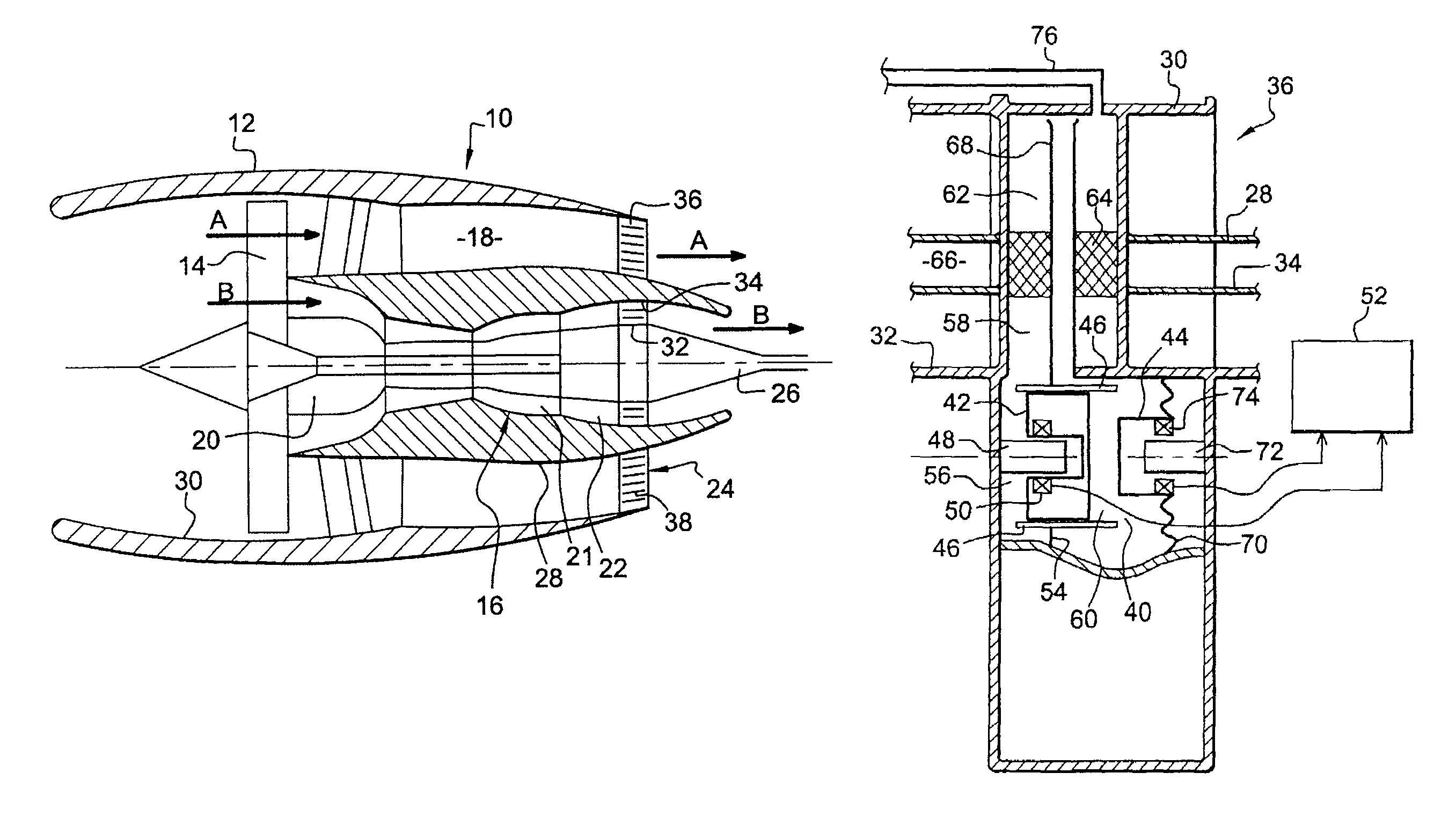
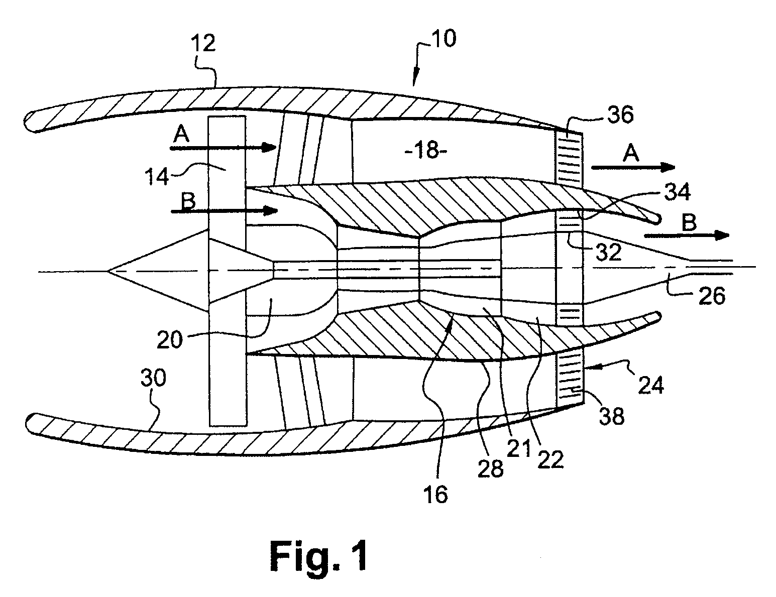
[0031]FIG. 1 represents a dual-flow jet engine 10 comprising a nacelle 12 in which a fan wheel 14 is mounted upstream of an engine body 16 mainly comprising, from upstream to downstream, a compressor 20, a combustion chamber 21, a turbine 22, an exhaust casing 24 and an ejection cone 26.

[0032]The fan wheel 14 is driven rotation-wise by the turbine 22 of the jet engine, in a manner well known to those skilled in the art. While the engine is operating, the fan 14 generates a secondary flow of air A, which flows backward around the jet engine in a fan duct 18, and which supplies a part of the engine thrust. A portion of the air entering the engine forms a primary flow B which feeds the inlet compressor 20 of the jet engine, then is mixed with fuel in the combustion chamber 21. The combustion gases leaving the combustion chamber drive the turbine 22 then are ejected between two coaxial walls 32, 34 of the exhaust casing 24 and leave the jet engine, flowing along the ejection cone 26.

[00...


PUM


Abstract

A turbomachine comprising at least one Stirling cycle thermal engine which is mounted at the end of a radial arm of the exhaust casing and comprises a working chamber located outside the primary and secondary flows, a displacing piston associated with a moving element of an energy generation system, and two exchangers, heating and cooling, formed in parts of the radial arm respectively intercepting the primary flow and the secondary flow, these two exchangers communicating with each other and with the working chamber for the circulation of a working fluid.

Description

BACKGROUND OF THE INVENTION[0001]The present invention relates to electricity generation in turbomachines, in particular dual-flow turbomachines, such as airplane jet engines.[0002]The electrical power supply for airplanes is generally provided by electromechanical generators incorporated in the jet engines of these airplanes and driven by power taken from high-pressure compressors of the jet engines.[0003]Since the mechanical power tapped in this way is not used for propulsion, this type of electrical generator substantially lowers the efficiency of the jet engines.DESCRIPTION OF THE PRIOR ART[0004]Already known is a method of driving an electrical generator by means of an engine operating according to a Stirling cycle, but such a generator is a heavy machine designed to operate in co-generation mode with heating means for residential or office buildings as described, for example, in the document GB-A-2 391 299, and is not suited to use on an aeronautical turbomachine. The main aim...

Claims


Application Information

Patent Timeline
Patent Type & Authority Patents(United States)
IPC IPC(8): F02C6/00
CPCF02C6/18F02C7/32Y02E20/14Y02T50/60
Inventor FOUCAULT, ALAIN AUGUSTE JACQUESJUCHAULD, ETIENNEPIERROT, ARNAUD JEAN-MARIEROUSSELIN, STEPHANE
Owner SN DETUDE & DE CONSTR DE MOTEURS DAVIATION S N E C M A
Why Eureka
Try Eureka