Method of fabricating a casing for turbine stator

a casing and stator technology, applied in the direction of turbines, liquid fuel engines, forging/pressing/hammering apparatus, etc., can solve the problems of not enabling the reduction of the heating of the shroud, the bulky equipment, and the lack of significant reduction of the manufacture. , to achieve the effect of good mechanical properties and good dimensional precision

Active Publication Date: 2010-03-30
SN DETUDE & DE CONSTR DE MOTEURS DAVIATION S N E C M A
View PDF11 Cites 33 Cited by
  • Summary
  • Abstract
  • Description
  • Claims
  • Application Information

AI Technical Summary

Benefits of technology

[0007]The invention relates to a method of fabricating a turbine stator casing that enables double-skinned casing shrouds to be made with good dimensional precision, said shrouds also presenting good mechanical properties.
[0016]The fact that the shroud is made by hot isostatic pressing (HIP) to a metallic powder enables a part to be obtained directly to the desired dimensions with great precision.
[0020]The inserts enable the air flow paths formed by dissolving the cores to be interconnected, thereby facilitating the flow of cool air and thus the cooling of the shroud.

Problems solved by technology

Nevertheless, in practice, it has been found that such a cooling system requires equipment that is bulky and expensive and does not enable the heating of the shroud to be reduced significantly at its inside face.
That method of manufacture nevertheless presents certain drawbacks associated with the very nature of manufacture by casting.
Thus, it is difficult to control the dimensional precision of the shroud casting.
In addition, mechanical properties such as elastic limit and fatigue resistance of the resulting shroud are not good, often because of its high degree of porosity or because of the presence of structural defects in its bulk that weaken it (these defects are often associated with the casting cooling in non-uniform manner).

Method used


Image

  • Method of fabricating a casing for turbine stator
  • Method of fabricating a casing for turbine stator
  • Method of fabricating a casing for turbine stator

Examples


Embodiment Construction

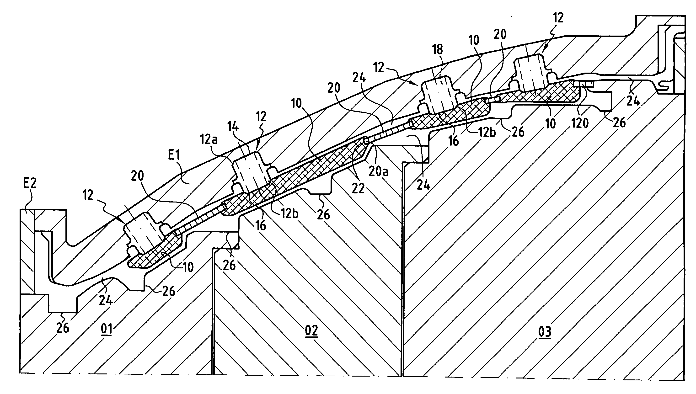
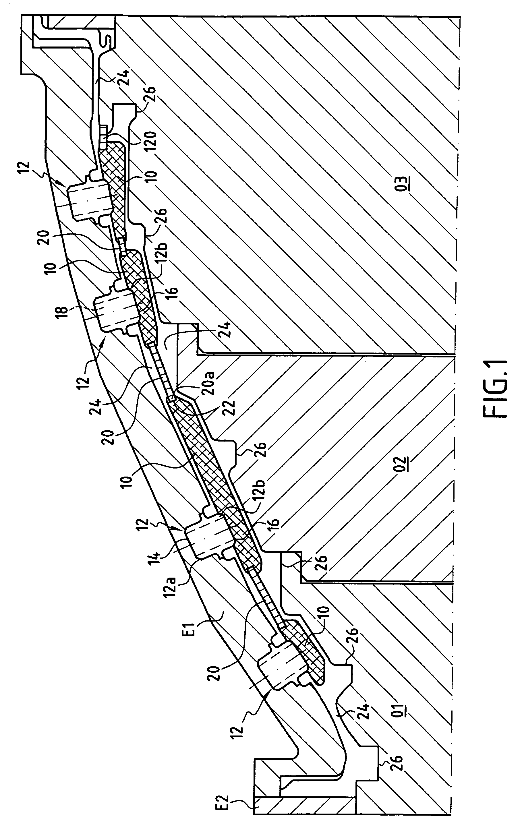
[0026]The tooling shown in FIG. 1 comprises a mold made up of several parts. Five of the parts are shown: three inner parts O1, O2, and O3, and two outer parts E1 and E2. The design of these mold parts is very precise. This design is computer-assisted and takes account of the local shrinkage that occurs during hot isostatic pressing. This particular HIP technique is better known under the name “Isoprec® method” (registered trademark), and enables a casing shroud to be obtained directly to its design dimensions, thereby limiting any subsequent machining thereof.

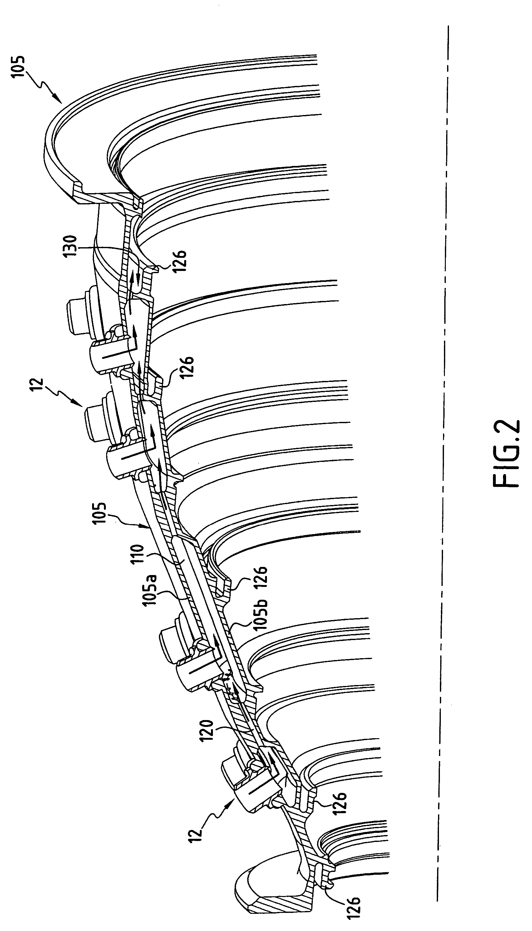
[0027]Cores 10 made of a material that is soluble in a particular solvent are secured to the outer mold shroud portion E1 by tubular pegs 12. These pegs 12 hold the cores 10 in position, where the empty spaces 110 for passing a flow of cool air are to be located in the thickness of the shroud 105.

[0028]Each core 10 is in the form either of a ring, or a ring segment (each segment being suitable for being placed end to end with ...


PUM

PropertyMeasurementUnit
temperaturesaaaaaaaaaa
temperatureaaaaaaaaaa
pressureaaaaaaaaaa

Abstract

The invention provides a method of fabricating a turbine stator casing, the method comprising the operations consisting in: between the walls of portions of a mold, forming a cavity of shape corresponding to the shape of the shroud of said casing, securing soluble cores to at least one of said mold portions, said cores being held at a distance from the wall of said mold portion and representing empty spaces that are to be formed inside said shroud; putting soluble inserts into place between the cores to represent flow paths between said empty spaces; filling said cavity with a metal alloy powder; sintering said powder by hot isostatic pressing; eliminating the cores and the inserts by dissolving them; and extracting the shroud as molded in this way. The invention is applicable to fabricating a turbine stator casing for an airplane turbojet.

Description

[0001]The invention relates to a method of fabricating a stator casing for a turbine, and more particularly for an airplane turbojet turbine.BACKGROUND OF THE INVENTION[0002]Such a casing comprises a shroud of generally frustoconical shape which carries fastener hooks on its inside face, i.e. facing towards the inside of the turbine, for holding one or more turbine nozzles formed by rings or ring segments carrying stationary vanes. Rotary wheels carrying the moving blades of the turbine rotor are located between such nozzles. Each pair constituted by a nozzle and a rotary wheel constitutes a stage of the turbine.[0003]Turbines, and more particularly airplane turbojet turbines, have very hot combustion gases passing through them at temperatures that can sometimes be as great as 1100° C. in certain turbine stages. The shroud of the casing is thus subjected to very significant heating and it is necessary to cool it using a cooling system.[0004]The European patent application published ...

Claims


Application Information

Patent Timeline
Patent Type & Authority Patents(United States)
IPC IPC(8): B22F7/00B22F3/12B22F5/04F01D25/14F01D25/24F01D25/26
CPCB22F3/1258F01D25/14F01D25/24B22F5/04Y02T50/671B22F2999/00Y02T50/675Y10T29/4932Y10T29/49346F05D2230/22F05D2230/21B22F5/10B22F3/15Y02T50/60
Inventor IMBOURG, SEBASTIENMONS, CLAUDEPABION, PHILIPPESOUPIZON, JEAN-LUC
Owner SN DETUDE & DE CONSTR DE MOTEURS DAVIATION S N E C M A
Why Eureka
Try Eureka