Photo-multiplier tube removal tool

a technology for multi-plier tubes and tools, which is applied in the direction of screwdrivers, electric discharge tubes, wrenches, etc., can solve the problems of severe damage to pmts and damage to pmts, and achieve the effects of safe and efficient removal, easy gripping of the handle, and reducing the time it takes to remov

Inactive Publication Date: 2010-04-13
SIEMENS MEDICAL SOLUTIONS USA INC
View PDF9 Cites 10 Cited by
  • Summary
  • Abstract
  • Description
  • Claims
  • Application Information

AI Technical Summary

Benefits of technology

[0009]It is an aspect of the present disclosure to provide for a tool and process for the damage-free removal of PMTs during the refurbishment and / or repair of detectors. A further aspect of the present disclosure is to provide channel lock pliers that preferably grab the base of the PMT with the pliers and by applying a rotating motion, the PMT can effectively be released in a damage-free manner.
[0010]In accordance with the above-noted aspects of the present disclosure, a PMT removal tool is presented. The PMT removal tool enables an easy grip handle for safe and efficient removal of PMTs. In an exemplary embodiment of the present disclosure, the PMT tool includes a clamping mechanism that fits precisely at the base of the PMT without damaging the PMT. The PMT removal tool further reduces the time it takes to remove a PMT compared to previous tool removal methods. Furthermore, the PMT removal tool allows for increased safety during the removal of a PMT, increased re-usability of the PMTs, and a significant cost reduction for the replacement of any PMTs.

Problems solved by technology

However, this method of using a gardener's trowel or a painting knife can cause severe damage to the PMTs during the removal process.
The variable forces applied to detach the PMT can easily damage PMTs during the refurbishment and / or repair of the detectors.

Method used


Image

  • Photo-multiplier tube removal tool
  • Photo-multiplier tube removal tool
  • Photo-multiplier tube removal tool

Examples


Embodiment Construction

[0017]The following description is presented to enable one of ordinary skill in the art to make and use the disclosure and is provided in the context of a patent application and its requirements. Various modifications to the disclosed embodiments will be readily apparent to those skilled in the art and the generic principles herein may be applied to other embodiments. Thus, the present disclosure is not intended to be limited to the embodiments shown but is to be accorded the broadest scope consistent with the principles and features described herein.

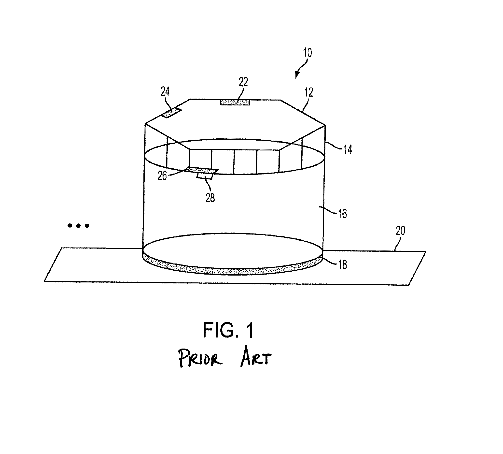
[0018]Referring to FIG. 1, a schematic illustration of a detector photo-multiplier tube (PMT) assembly is presented. The PMT assembly 10 includes a circuit board 12, PMT cable connectors 14, a metal shield 16, a gel adhesive 18, a light pipe 20, a capacitor attachment point 22, a bias voltage attachment point 24, an end cap 26, and an end cap notch 28.

[0019]The circuit board 12 includes at least a capacitor attachment point 22 and a bia...


PUM

PropertyMeasurementUnit
symmetryaaaaaaaaaa
surface profileaaaaaaaaaa
positron emission tomographyaaaaaaaaaa

Abstract

A tool is provided including a ratchet assembly including a handle grip and a socket; and a clamping assembly including a clamp with a notch; wherein the ratchet assembly is configured to be affixed to the clamping assembly so that a rotatable force applied to the handle grip actuates the clamp.

Description

BACKGROUND[0001]1. Technical Field[0002]The present disclosure generally relates to photo-multiplier tubes (PMTs). In particular, the present disclosure relates to a tool and process for the removal of PMTs during the refurbishment and / or repair of photo-detectors or photo-sensors.[0003]2. Background of Related Art[0004]Nuclear medicine is a unique medical specialty wherein radiation is used to acquire images which show the function and anatomy of organs, bones or tissues of the body. Radiopharmaceuticals are introduced into the body, either by injection or ingestion, and are attracted to specific organs, bones or tissues of interest. Such radiopharmaceuticals produce gamma photon emissions which emanate from the body and are detected by a radiation detector, such as a positron emission tomography (PET) camera.[0005]Conventional PET cameras utilize a scintillation crystal, which absorbs the gamma photon emissions and emits light photons (or light events) in response to the gamma abs...

Claims


Application Information

Patent Timeline
Patent Type & Authority Patents(United States)
IPC IPC(8): B25B13/48B25B13/02
CPCB25B13/48H01J43/00Y10T29/49721
Inventor FLORES, THOMAS H.HANRAHAN, WILLIAM J.
Owner SIEMENS MEDICAL SOLUTIONS USA INC
Why Eureka
Try Eureka