Patterned metal thermal interface

a thermal interface and metal technology, applied in the direction of electrical apparatus construction details, basic electric elements, lighting and heating apparatus, etc., can solve the problems of material attack or diffuse into other materials, materials may fail to wet other materials, silicon, silicon, etc., and achieve the effect of convenient removal during rework and easy cleaning

Active Publication Date: 2010-04-13
GLOBALFOUNDRIES US INC
View PDF5 Cites 18 Cited by
  • Summary
  • Abstract
  • Description
  • Claims
  • Application Information

AI Technical Summary

Benefits of technology

[0006]The present invention is a patterned metal thermal interface. In one embodiment a system for dissipating heat from a heat-generating device includes a heat sink having a first surface adapted for thermal coupling to a first surface of the heat generating device and a thermal interface formed a soft metal and having at least one patterned surface, the thermal interface being adapted to thermally couple the first surface of the heat sink to the first surface of the heat generating device. Patterning refers to an arrangement of local thick and thin spots on an otherwise flat foil or sheet of metal interface material. Many patterns are possible, and the precise distribution of thick and thin spots is chosen based on the application to give statistical uniformity. The patterned surface of the thermal interface allows the thermal interface to deform under compression between the heat sink and the heat generating device, leading to better conformity of the contact points of the thermal interface to the surfaces of the heat sink and the heat generating device.
[0010]Since most heat sinks are clamped to heat-generating devices with significant force (e.g., 20 pounds or more) in order to compress thermal greases, the patterned metal thermal interface provides a practical high performance alternative with little or no change to existing assemblies. Pressure and optional heating are present during the application of the patterned metal interface. Once the thermal interface has been applied and bonded to the heat-generating device and to the heat sink, optional maintenance of pressure leads to better mechanical stability and robustness of the assembly. Reducing the amount of surface oxide on all mating surfaces of the heat-generating device and the heat sink prior to assembly further improves the thermal performance of the thermal interface.
[0011]The patterned metal thermal interface is intended as a general thermal interface solution. One particular area in which the thermal interface of the present invention may find use is between a computer chip comprised of silicon (and typically coated with silicon dioxide or silicon nitride) and a heat sink comprised of copper, nickel-plated copper or aluminum. A second area in which the thermal interface of the present invention may find use is between a lidded computer chip and a heat sink (similar to the heat sink described above), where the lid of the computer chip is comprised of copper or nickel-plated copper. Thus, the mating surfaces to be thermally coupled will, in many cases, be comprised of copper, nickel or silicon. In one embodiment, where the patterned metal thermal interface is comprised of indium or tin, the thermal interface can be directly applied to copper, nickel and silicon surfaces. In another embodiment, where the patterned metal thermal interface is comprised of silicon, a surface metallization is optionally applied to promote bonding and improve the thermal contact performance. If pressure is maintained during use, surface metallization of the thermal interface is not absolutely necessary, but will improve the thermal performance and reduce corrosion susceptibility.

Problems solved by technology

In some cases, these materials can attack or diffuse into other materials such as aluminum or copper, which are common heat sink materials.
In other cases, these materials may fail to wet other materials such as silicon, silicon dioxide, silicon nitride or the like, which are common chip materials.
De-wetting or degradation of the interface between the STI material and the heat sink, or between the STI material and the chip, can produce local hot spots that impede the thermal performance or cause outright failure of the chip in high-power applications.
This is often difficult or impractical to achieve.
Moreover, in cases where melting points exceed 125 degrees Celsius, attaching a heat sink would likely result in component failure.

Method used


Image

  • Patterned metal thermal interface
  • Patterned metal thermal interface
  • Patterned metal thermal interface

Examples


Embodiment Construction

[0023]In one embodiment, the present invention is a thermal interface for use in dissipating heat from heat-generating devices (e.g., microprocessor chips). Embodiments of the present invention provide improved heat transfer from a heat generating device to a heat sink, thereby allowing for better heat dissipation from the heat generating device. This ultimately results in better performance of the heat generating device, as heat-related failures are minimized.

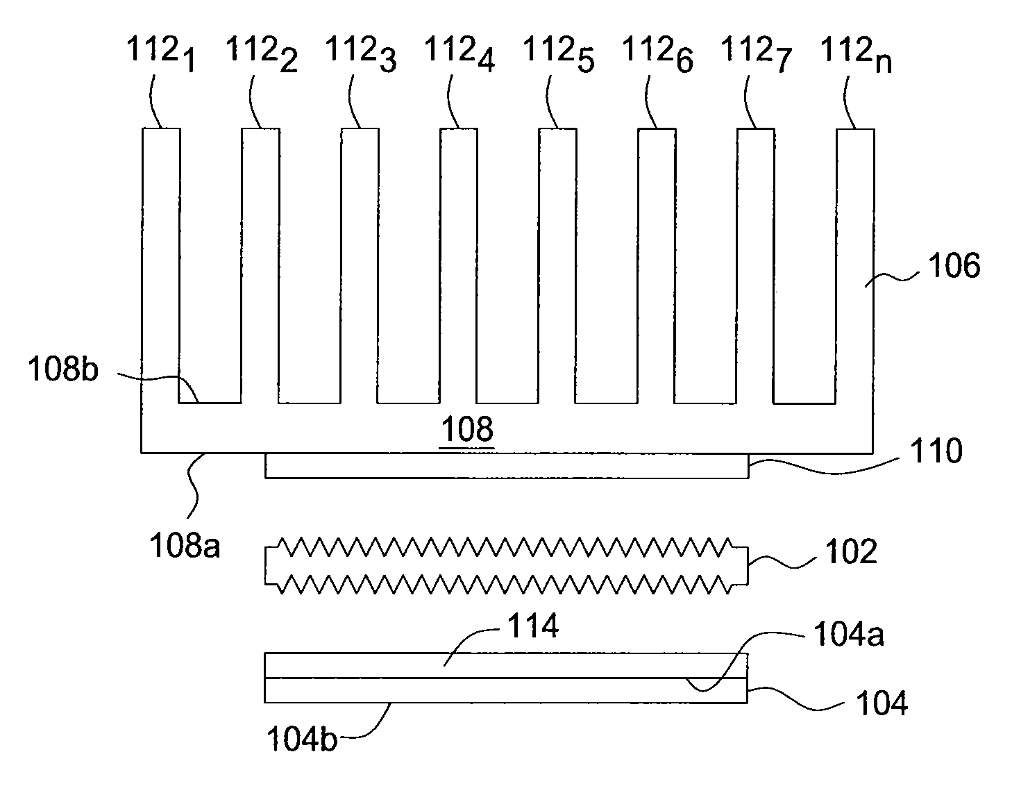
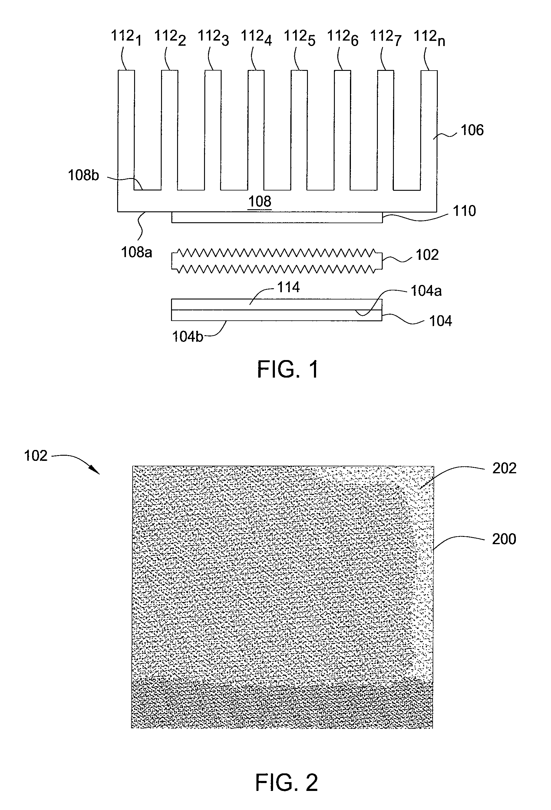
[0024]FIG. 1 is an exploded view of a heat sink assembly 100 using a patterned metal thermal interface 102, according to one embodiment of the present invention. As illustrated, the heat sink assembly 100 comprises the thermal interface 102 disposed between a heat generating device 104 (e.g., a microprocessor chip or a lidded chip) and a heat sink 106. Alternatively, the heat sink 106 may be a lid where the heat generating device 104 is a microprocessor or semiconductor chip.

[0025]The heat sink 106 comprises a base 108 having ...


PUM

PropertyMeasurementUnit
temperatureaaaaaaaaaa

Abstract

The present invention is a patterned metal thermal interface. In one embodiment a system for dissipating heat from a heat-generating device includes a heat sink having a first surface adapted for thermal coupling to a first surface of the heat generating device and a thermal interface having at least one patterned surface, the thermal interface being adapted to thermally couple the first surface of the heat sink to the first surface of the heat generating device. The patterned surface of the thermal interface allows the thermal interface to deform under compression between the heat sink and the heat generating device, leading to better conformity of the thermal interface to the surfaces of the heat sink and the heat generating device.

Description

FIELD OF THE INVENTION[0001]The present invention relates generally to microprocessor and integrated circuits, and relates more particularly to the cooling of integrated circuit (IC) chips.BACKGROUND OF THE INVENTION[0002]Recent years have seen an evolution toward higher-power microprocessor, graphics, communication and memory semiconductor chips. This evolution in turn has driven interest in highly conductive solder thermal interface (STI) materials and liquid metal thermal interface (LMI) materials to provide improved thermal coupling between a chip and a heat sink. In both cases, it is an essential function of the thermal interface material that it thermally couple and adhere both to the chip and to the heat sink, in order to reduce the occurrence of failure in use (e.g., due to poor heat transfer between the chip and the heat sink).[0003]A distinguishing feature of STI materials (which are understood to include low-melt solder materials that are solid at room temperature but may...

Claims


Application Information

Patent Timeline
Patent Type & Authority Patents(United States)
IPC IPC(8): F28F7/00
CPCH01L23/433F28F13/00Y10T29/4935H01L2224/73253Y10T29/53113F28F2013/005
Inventor FURMAN, BRUCE K.IRUVANTI, SUSHUMNALAURO, PAUL A.MARTIN, YVES C.SHIH, DA YUANVAN KESSEL, THEODORE G.ZOU, WEI
Owner GLOBALFOUNDRIES US INC
Why Eureka
Try Eureka