Indexable insert

a technology of indexable inserts and inserts, which is applied in the direction of cutting inserts, superimposed coating processes, manufacturing tools, etc., can solve the problems of deteriorating and no attempt has been made to solve the problem, so as to prevent deterioration of the surface state of the workpiece. , the effect of decreasing

Active Publication Date: 2010-04-13
SUMITOMO ELECTRIC HARDMETAL CORP
View PDF10 Cites 24 Cited by
  • Summary
  • Abstract
  • Description
  • Claims
  • Application Information

AI Technical Summary

Benefits of technology

[0017]The indexable insert of the present invention has the above-described constitution and is thus successful in decreasing as much as possible welding between the coating layer formed on the substrate and the workpiece, and accordingly preventing deterioration in the surface state of the workpiece.

Problems solved by technology

However, this attempt has caused the problem of welding of the outermost layer used for identifying the use state and a workpiece during cutting, thereby degrading the surface state of the workpiece.
However, substantially no attempt has been made to resolving the problem.

Method used


Image

  • Indexable insert
  • Indexable insert
  • Indexable insert

Examples


example 1

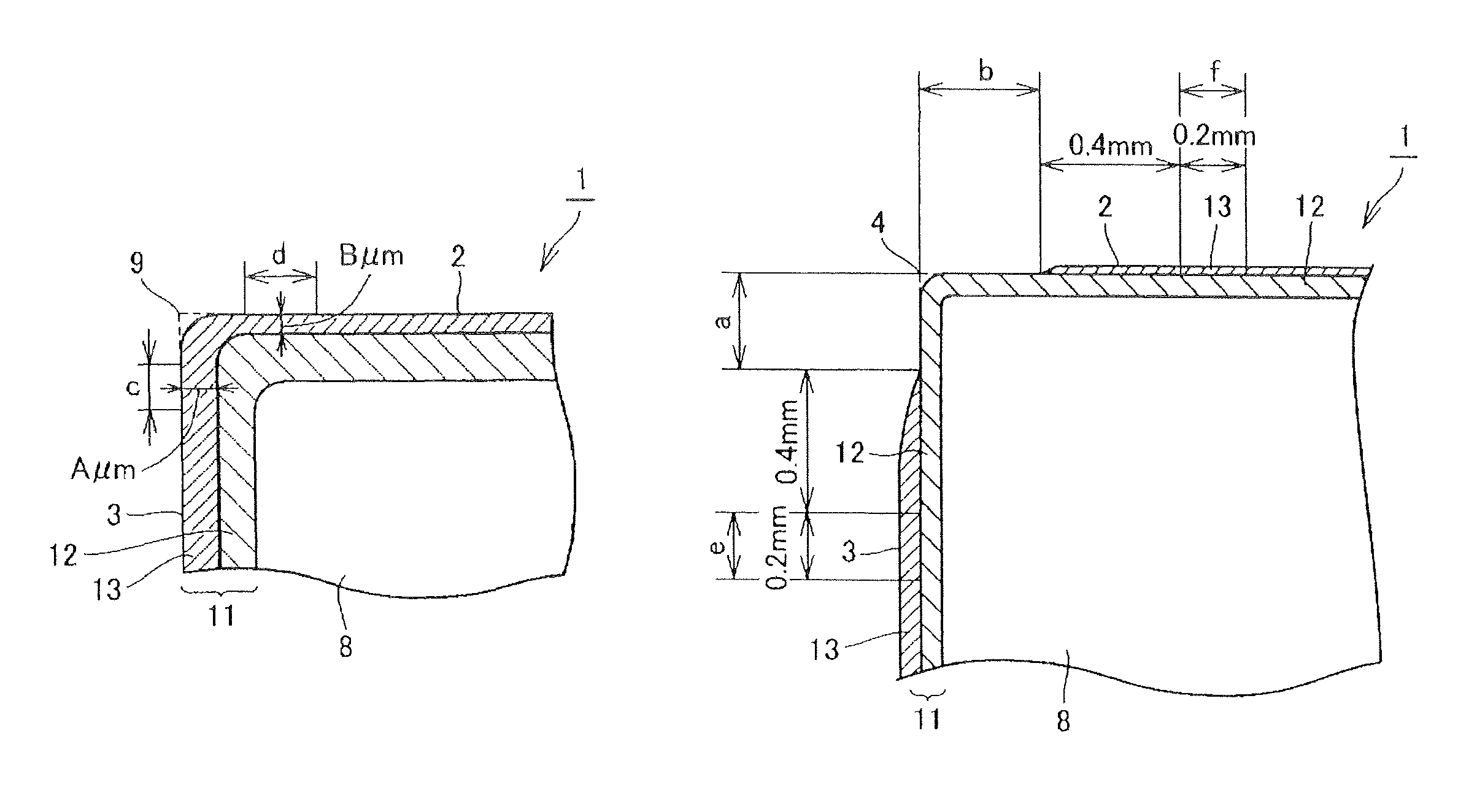
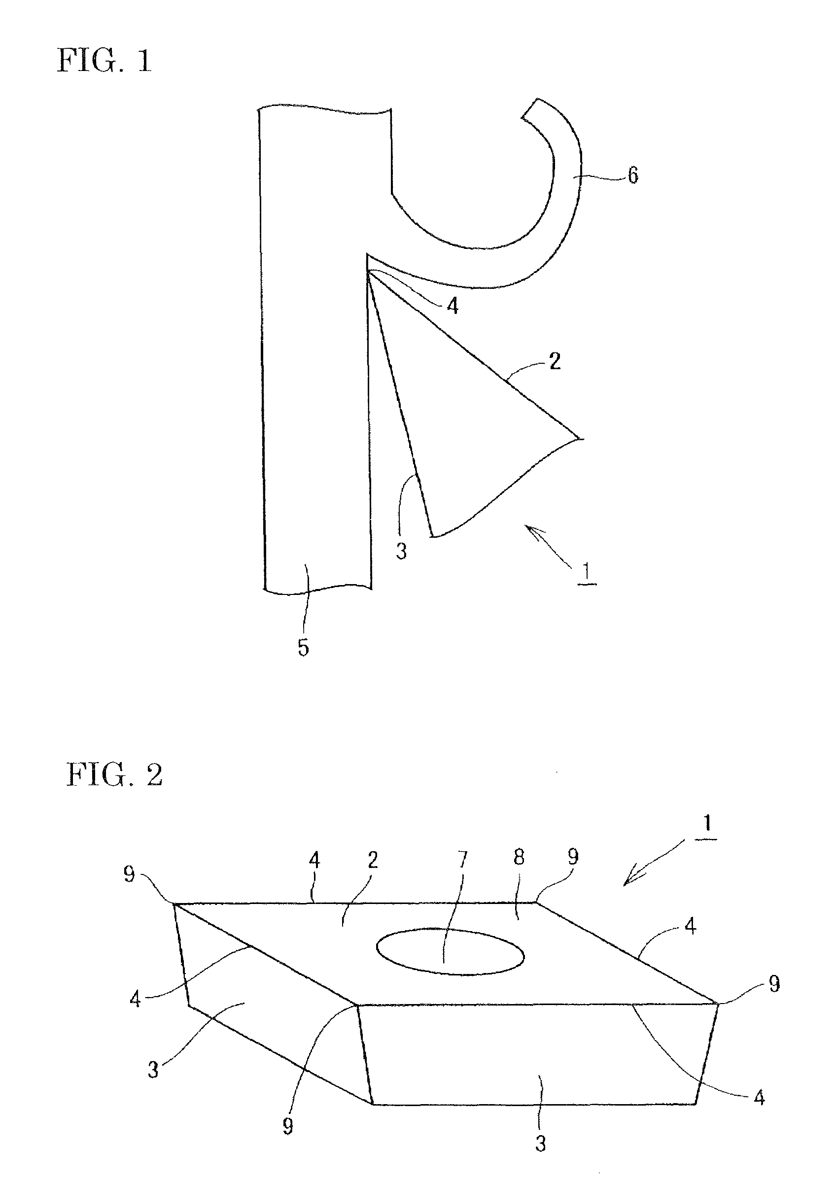
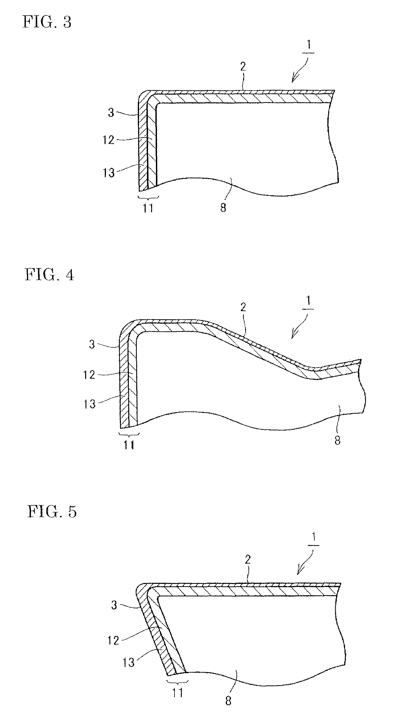
[0100]A cemented carbide powder with a composition containing 2.0% by mass of TiC, 1.2% by mass of TaC, 1.5% by mass of NbC, 8.0% by mass of Co, and the balance WC was pressed, sintered at 1400° C. for 1 hour in a vacuum atmosphere, and then subjected to smooth polishing and edge processing of an edge line with a SiC brush (horning of a width of 0.05 mm from the rake face side) to prepare a cemented carbide tip as a substrate having the same shape as a cutting tip CNMG120408N-UX (manufactured by Sumitomo Electric Hardmetal Corp.). The substrate had a beta-free layer of 17 μm formed on the surface thereof, two rake faces, and four flank faces, each rake face and each flank face being connected with an edge line (a hypothetical line because the edge processing had been performed) provided therebetween. The substrate had a total of eight edge lines. In addition, a point of intersection of two flank faces and one rake face was a corner (a hypothetical point of intersection because the e...

example 2

[0150]A cemented carbide powder with a composition containing 0.5% by mass of TiC, 0.4% by mass of TaC, 0.2% by mass of NbC, 5.0% by mass of Co, and the balance WC was pressed, sintered at 1450° C. for 1 hour in a vacuum atmosphere, and then subjected to smooth polishing and edge processing of edge lines with a SiC brush (horning of a width of 0.05 mm from the rake face side) to prepare a cemented carbide tip as a substrate having the same shape as a cutting tip CNMA120408 defined by JIS B4120 (revised in 1998). The substrate had neither chip breaker nor beta-free layer formed on the surface thereof, and had two rake faces, and four flank faces, each rake face and each flank face being connected with an edge line (a hypothetical line because the edge processing had been performed) provided therebetween. The substrate had a total of eight edge lines. In addition, a point of intersection of two flank faces and one rake face was a corner (a hypothetical point of intersection because th...

example 3

[0184]A cemented carbide powder with a composition containing 1.5% by mass of TaC, 10.0% by mass of Co, and the balance WC was pressed, sintered at 1400° C. for 1 hour in a vacuum atmosphere, and then subjected to smooth polishing and edge processing of edge lines with a SiC brush (horning of a width of 0.05 mm from the rake face side) to prepare a cemented carbide tip as a substrate having the same shape as a cutting tip SEMT13T3AGSN-G (manufactured by Sumitomo Electric Hardmetal Corp.). The substrate had no beta-free layer formed on the surface thereof, one rake face, and four flank faces, the rake face and each flank face being connected with the edge line (a hypothetical line because the edge processing had been performed) provided therebetween. The substrate had a total of four edge lines. In addition, a point of intersection of two flank faces and one rake face was a corner (a hypothetical point of intersection because the edge processing had been performed). The substrate had...


PUM

PropertyMeasurementUnit
thicknessaaaaaaaaaa
distanceaaaaaaaaaa
distanceaaaaaaaaaa

Abstract

An indexable insert (1) of the present invention includes a substrate (8) and a coating layer which includes inner layer and an outer layer. The inner layer includes an alumina layer or an alumna-containing layer serving as an outermost layer in contact with the outer layer, and the outer layer is composed of at least one metal selected from the group consisting of the periodic table group IVa elements, Va elements, and VIa elements, Al, and Si or a compound of at least one of the metals and at least one element selected from the group consisting of carbon, nitrogen, oxygen, and boron. In addition, the outer layer, in a portion involved in cutting, satisfies B / A≦0.9 wherein A μm is the average thickness on the flank face (3) side, and B μm is the average thickness on the rake face (2) side.

Description

TECHNICAL FIELD[0001]The present invention relates to an indexable insert (also referred to as a “throw-away tip”).BACKGROUND ART[0002]Indexable inserts to be detachably mounted on tools for cutting workpieces have been known. As such indexable inserts, many cutting tips each including a substrate composed of a cemented carbide or cermet and a hard coating of ceramic formed thereon for improving wear resistance and toughness have been proposed.[0003]In such indexable inserts, various attempts have been made to improve characteristics by changing the composition of a hard coating or differentiating the thickness of the hard coating on a flank face from that on a rake face (Japanese Unexamined Patent Application Publication No. 2001-347403 (Patent Document 1), Japanese Unexamined Patent Application Publication No. 2004-122263 (Patent Document 2), Japanese Unexamined Patent Application Publication No. 2004-122264 (Patent Document 3), and Japanese Unexamined Patent Application Publicati...

Claims


Application Information

Patent Timeline
Patent Type & Authority Patents(United States)
IPC IPC(8): B23B27/14B23B51/00
CPCB23B27/143B23B27/145C23C28/042C23C28/044C23C30/005B23B2200/201B23B2228/105Y10T407/23Y10T407/27B23B27/14B23B27/00
Inventor OMORI, NAOYAOKADA, YOSHIOITOH, MINORUOKUNO, SUSUMUIMAMURA, SHINYA
Owner SUMITOMO ELECTRIC HARDMETAL CORP
Why Eureka
Try Eureka