Powertrain control apparatus and method

a technology of powertrain and control apparatus, applied in electrical control, gearing, instruments, etc., can solve the problems of long time until the engine speed starts increasing, low fuel combustibility, lag between, etc., and achieve the effect of suppressing a shock and suppressing an engine stall

Inactive Publication Date: 2010-04-20
TOYOTA JIDOSHA KK
View PDF7 Cites 3 Cited by
  • Summary
  • Abstract
  • Description
  • Claims
  • Application Information

AI Technical Summary

Benefits of technology

[0010]The invention provides a powertrain control apparatus and method that suppresses a shock when fuel supply resumes, and suppresses an engine stall.
[0012]According to the first aspect of the invention, the lock-up clutch is brought to the disengaged state from the engaged state when the output unit outputs the instruction. However, there is a lag between the time the lock-up clutch is completely disengaged and when the process of disengaging the lock-up clutch starts. Therefore, the fuel supply to the engine resumes when the preset lag time has passed after the instruction is output. The time from when the fuel supply resumes until when the engine speed starts increasing varies depending on the temperature of the combustion chamber of the engine. When the temperature of the combustion chamber is low, the combustibility of fuel is low. Therefore, the time until when the engine speed starts increasing is long. When the temperature of the combustion chamber is high, the combustibility of fuel is high. Therefore, the time until when the engine speed starts increasing is short. Thus, the lag time between when the instruction is output, and when the fuel supply resumes is set so that the lag time is shorter when the temperature of the combustion chamber of the engine is the first temperature than when the temperature of the combustion chamber of the engine is the second temperature which is higher than the first temperature. For example, the lag time may be set based on the temperature of the coolant of the engine or the period of time over which the fuel supply is cut off. The lag time is set to decrease as the temperature of the coolant of the engine decreases. Alternatively, the lag time is set to decrease as the period of time over which the fuel supply is cut off increases. Thus, when the temperature of the combustion chamber of the engine is low and the period until the engine starts increasing is long, the engine is controlled so that the fuel supply resumes sooner. In contrast, when the temperature of the combustion chamber of the engine is high and the period until when the engine speed starts increasing is short, the engine is controlled so that the fuel supply resumes later. This reduces the deviation between the timing at which the lock-up clutch is actually disengaged, and the timing at which the engine speed starts increasing. As a result, it is possible to provide the powertrain control apparatus that suppresses a shock when the fuel supply resumes, and prevents the engine from stalling.
[0015]The powertrain control apparatus according to the third aspect of the invention is similar to the control apparatus according to the first aspect, except that the setting unit decreases the lag time as the temperature of the coolant decreases.
[0016]According to the third aspect of the invention, the lag time is set to decrease as the temperature of the coolant of the engine decreases. Thus, when the temperature of the combustion chamber of the engine is low and the time until the engine speed starts increasing is long, the engine is controlled so that the fuel supply resumes sooner. In contrast, when the temperature of the combustion chamber of the engine is high and the time until the engine speed starts increasing is short, the engine is controlled so that the fuel supply resumes later. This reduces the deviation between the timing at which the lock-up clutch is actually disengaged, and the timing at which the engine speed starts increasing. As a result, it is possible to provide the powertrain control apparatus, which suppresses a shock when the fuel supply resumes, and suppresses an engine stall.
[0019]The powertrain control apparatus according to the fifth aspect of the invention is similar to the control apparatus according to the fourth aspect, except that the setting unit decreases the lag time as the period of time over which the fuel supply is cut off increases.
[0020]According to the fifth aspect of the invention, the lag time is set to decrease as the period of time over which the fuel supply is cut off increases. Thus, when the temperature of the combustion chamber of the engine is low and the period until the engine starts increasing is long, the engine is controlled so that the fuel supply resumes sooner. In contrast, when the temperature of the combustion chamber of the engine is high, and the period until when the engine speed starts increasing is short, the engine is controlled so that the fuel supply resumes later. This reduces the deviation between the timing at which the lock-up clutch is actually disengaged, and the timing at which the engine speed starts increasing. As a result, it is possible to provide a powertrain control apparatus that suppresses a shock when the fuel supply resumes, and suppresses an engine stall.

Problems solved by technology

However, there is a lag between the time the lock-up clutch is completely disengaged and when the process of disengaging the lock-up clutch starts.
When the temperature of the combustion chamber is low, the combustibility of fuel is low.
Therefore, the time until when the engine speed starts increasing is long.
When the temperature of the combustion chamber is high, the combustibility of fuel is high.
Therefore, the time until when the engine speed starts increasing is short.

Method used


Image

  • Powertrain control apparatus and method
  • Powertrain control apparatus and method
  • Powertrain control apparatus and method

Examples


Embodiment Construction

[0029]Hereinafter, embodiments of the invention will be described in detail with reference to the drawings. In the following description, the same components are denoted by the same reference numerals, and have the same names and the same functions. Therefore, redundant description thereof will be omitted.

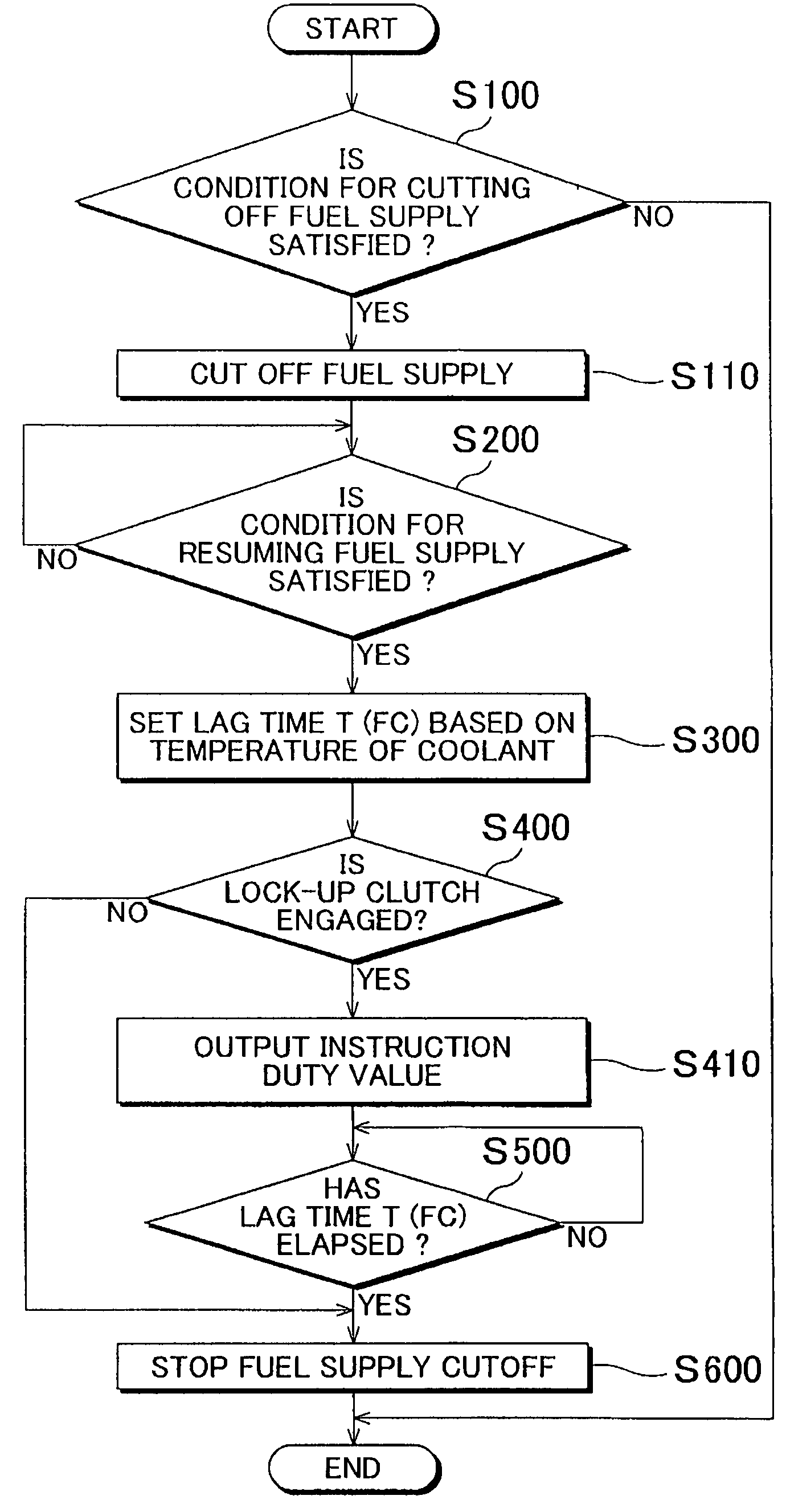
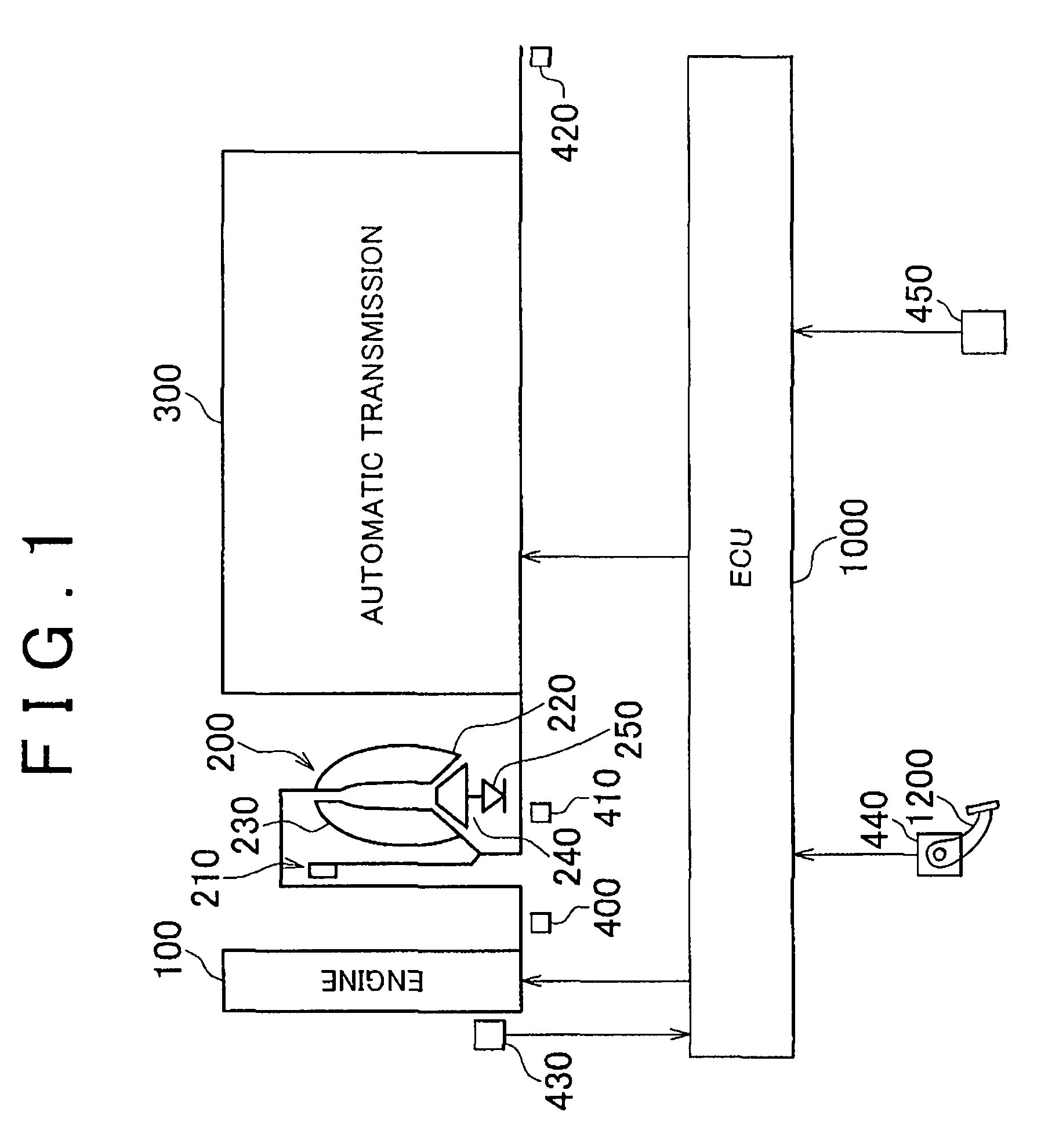
[0030]The powertrain of a vehicle in which a control apparatus according to a first embodiment of the invention is provided will be described with reference to FIG I. The control apparatus according to the embodiment may be realized, for example, when an ECU (electronic control unit) 1000 shown in FIG. 1 executes programs.

[0031]As shown in FIG. 1, the powertrain of the vehicle includes an engine 100, a torque converter 200, an automatic transmission 300, and an ECU 1000.

[0032]The output shaft of the engine 100 is connected to the input shaft of the torque converter 200. That is, the engine 100 is connected to the torque convert 200 by the rotational shafts. Accordingly, the rotatio...


PUM


Abstract

A powertrain control apparatus that controls a powertrain including a lock-up clutch, which connects an engine, in which fuel supply may be cut off, directly to an automatic transmission. The control apparatus includes an output unit, a control unit, and a setting unit. The output unit outputs an instruction to lower engagement pressure for the lock-up clutch from a value at which the lock-up clutch is engaged to a value at which the lock-up clutch is disengaged. The control unit resumes the fuel supply to the engine when a predetermined lag time has elapsed since the instruction is output. The setting unit sets the lag time so that the lag time is shorter when a temperature of a combustion chamber of the engine is a first temperature than when the temperature of the combustion chamber of the engine is a second temperature which is higher than the first temperature.

Description

INCORPORATION BY REFERENCE[0001]The disclosure of Japanese Patent Application No. 2006-067516 filed on Mar. 13, 2006, including the specification, drawings and abstract, is incorporated herein by reference in its entirety.BACKGROUND OF THE INVENTION[0002]1. Field of the Invention[0003]The invention relates to a powertrain control apparatus and method. More particularly, the invention relates to a powertrain that includes a lock-up clutch that connects an engine directly to an automatic transmission.[0004]2. Field of the Invention[0005]A conventional automatic transmission is connected to an engine via a fluid coupling such as a torque converter. The torque converter transmits the driving force to the transmission through the fluid (e.g., oil) that circulates in the torque converter. Therefore, the rotational speed of the input shaft of the torque converter differs from the rotational speed of the output shaft of the torque converter. This may decrease the efficiency of transmitting ...

Claims


Application Information

Patent Timeline
Patent Type & Authority Patents(United States)
IPC IPC(8): F16H61/00B60W10/02G06F7/00G06F17/00F16H61/14B60W10/04F02D29/00F02D41/12F16H59/78
CPCB60W10/026B60W10/06B60W30/18072F02D35/025F02D41/0215F02D41/022F16H61/143F02D41/126Y10T477/79B60W2510/0676Y10T477/78Y10T477/75Y10T477/73
Inventor TAMURA, TADASHIHINO, AKIRAYUMOTO, TAKASHI
Owner TOYOTA JIDOSHA KK
Why Eureka
Try Eureka