Exposure system and pattern formation method using the same

a technology of pattern formation and exposure system, applied in the field of exposure system, can solve the problems of reducing the productivity and yield of the semiconductor device fabrication process, and achieve the effect of good shape and abnormal exposur

Inactive Publication Date: 2010-04-20
RPX CORP
View PDF16 Cites 0 Cited by
  • Summary
  • Abstract
  • Description
  • Claims
  • Application Information

AI Technical Summary

Benefits of technology

[0014]When a resist pattern in such a defective shape is used for etching a target film, the resultant pattern of the target film is also in a defective shape, which disadvantageously lowers the productivity and the yield in the fabrication process for semiconductor devices.
[0018]In the first exposure system, since the immersion liquid is circulated during the pattern exposure by the liquid supply section for supplying the immersion liquid onto the resist film, the variation in the temperature distribution otherwise caused during the exposure by the exposing light between a portion irradiated with the exposing light and a portion masked from the exposing light of the immersion liquid can be avoided, so as to make the temperature of the immersion liquid uniform. Specifically, when the temperature of the immersion liquid is changed by 1° C., the refractive index n is changed by approximately −1.0×10⁻⁴ through −1.0×10⁻³. The layout of interconnects has recently become more and more refined and complicated, and hole diameters and interconnect widths are finely or variously set to, for example, 10 through 200 nm. When a resist pattern is formed for forming a hole or an interconnect, the resolution of the resist pattern is affected by slight change of the refractive index caused by the temperature change of 1° C. As a result, it is difficult to precisely form a desired pattern. Therefore, when the immersion liquid used for the immersion lithography is stirred during the pattern exposure, the variation in the temperature of the immersion liquid can be reduced. For example, when the pooled immersion liquid is stirred at a rate of approximately 100 rpm through 1000 rpm during the pattern exposure, the influence of the temperature of the immersion liquid changed owing to energy applied by the exposing light can be reduced. The stirring rate is set depending upon the exposure, and for example, in forming resist patterns for respective layers of interconnects, a high stirring rate may be employed when the pattern density is relatively high and a low stirring rate may be employed when the pattern density is relatively low. Since the variation in the refractive index of the immersion liquid can be avoided by thus making the temperature of the immersion liquid uniform, abnormal exposure such as focus failure can be prevented. As a result, a resist pattern can be formed in a good shape by the immersion lithography.
[0020]In the second exposure system, since the immersion liquid is stirred during the exposure by the liquid stirring means of the liquid supply section for supplying the immersion liquid onto the resist film, the variation in the temperature distribution otherwise caused in the immersion liquid during the exposure between a portion irradiated with the exposing light and a portion masked from the exposing light of the immersion liquid can be avoided, and hence, the temperature of the immersion liquid can be made uniform. Therefore, since the variation in the refractive index of the immersion liquid can be avoided, abnormal exposure such as focus failure can be prevented. As a result, a resist pattern can be formed in a good shape by the immersion lithography.
[0024]In the pattern formation method of the invention, the immersion liquid is allowed to flow during the pattern exposure in the step of performing pattern exposure, and therefore, the variation in the temperature distribution otherwise caused by the exposing light during the pattern exposure between a portion irradiated with the exposing light and a portion masked from the exposing light of the immersion liquid can be avoided, so as to make the temperature of the immersion liquid uniform. Since the variation in the refractive index of the immersion liquid can be avoided by thus making the temperature of the immersion liquid uniform, abnormal exposure such as focus failure can be prevented. As a result, a resist pattern can be formed in a good shape by the immersion lithography.

Problems solved by technology

When a resist pattern in such a defective shape is used for etching a target film, the resultant pattern of the target film is also in a defective shape, which disadvantageously lowers the productivity and the yield in the fabrication process for semiconductor devices.

Method used


Image

  • Exposure system and pattern formation method using the same
  • Exposure system and pattern formation method using the same
  • Exposure system and pattern formation method using the same

Examples


embodiment 1

[0039]Embodiment 1 of the invention will now be described with reference to the accompanying drawings.

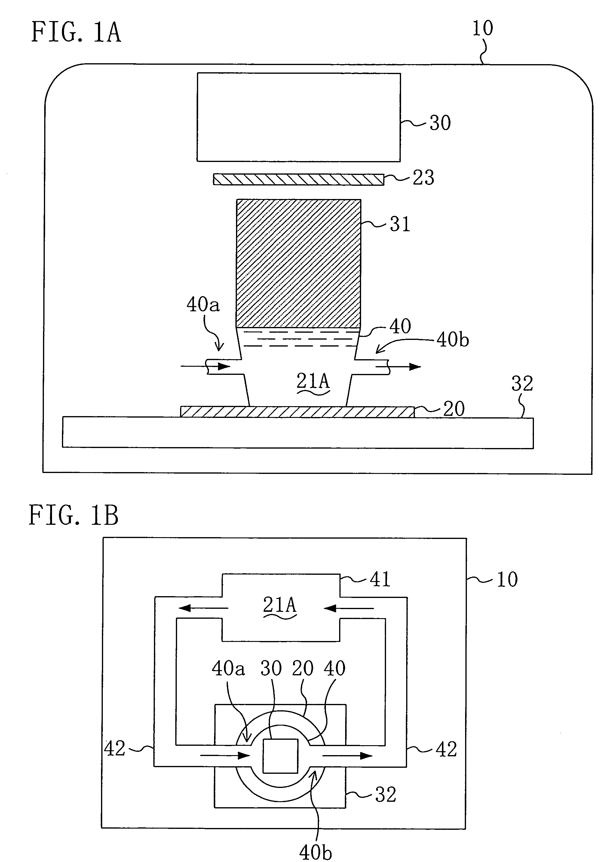
[0040]FIGS. 1A and 1B show a principal portion of an exposure system used for realizing a pattern formation method employing immersion lithography according to Embodiment 1 of the invention, and more specifically, FIG. 1A is a schematic cross-sectional view thereof and FIG. 1B is a schematic plan view thereof.

[0041]As shown in FIG. 1A, the exposure system of Embodiment 1 includes an illumination optical system 30 that is provided within a chamber 10 and works as a light source for exposing a design pattern on a resist film (not shown) applied on a wafer 20, and a bucket type liquid pooling section 40 that supplies an immersion liquid 21A, used for increasing the numerical aperture of exposing light, onto the wafer 20 during the exposure and has an inlet 40a and an outlet 40b.

[0042]Below the illumination optical system 30, a projection lens 31 for projecting the exposing light, whic...

embodiment 2

[0051]Embodiment 2 of the invention will now be described with reference to the accompanying drawings.

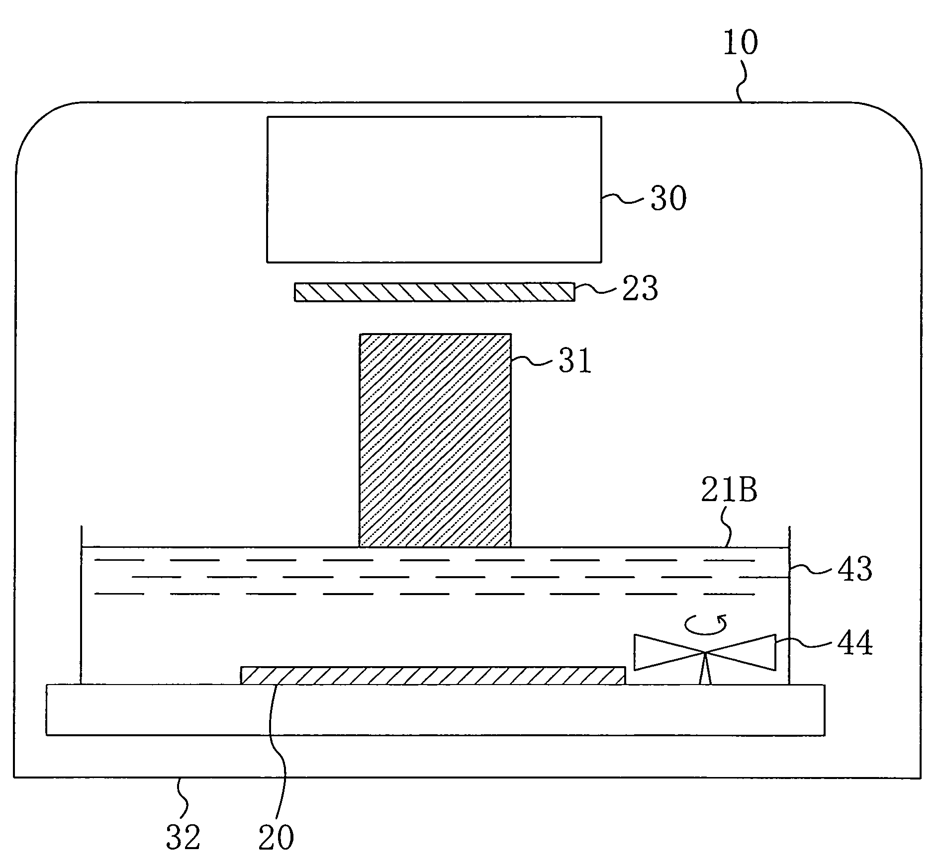
[0052]FIG. 3 shows a principal portion of an exposure system used for realizing a pattern formation method employing the immersion lithography according to Embodiment 2 of the invention. In FIG. 3, like reference numerals are used to refer to like elements shown in FIG. 1A so as to omit the description.

[0053]As shown in FIG. 3, the exposure system of Embodiment 2 includes a liquid pooling section 43 in the shape of a dip type vessel, and on the bottom of the liquid pooling section 43, a stirrer 44 for stirring an immersion liquid 21B pooled therein is provided in a position not disturbing exposure.

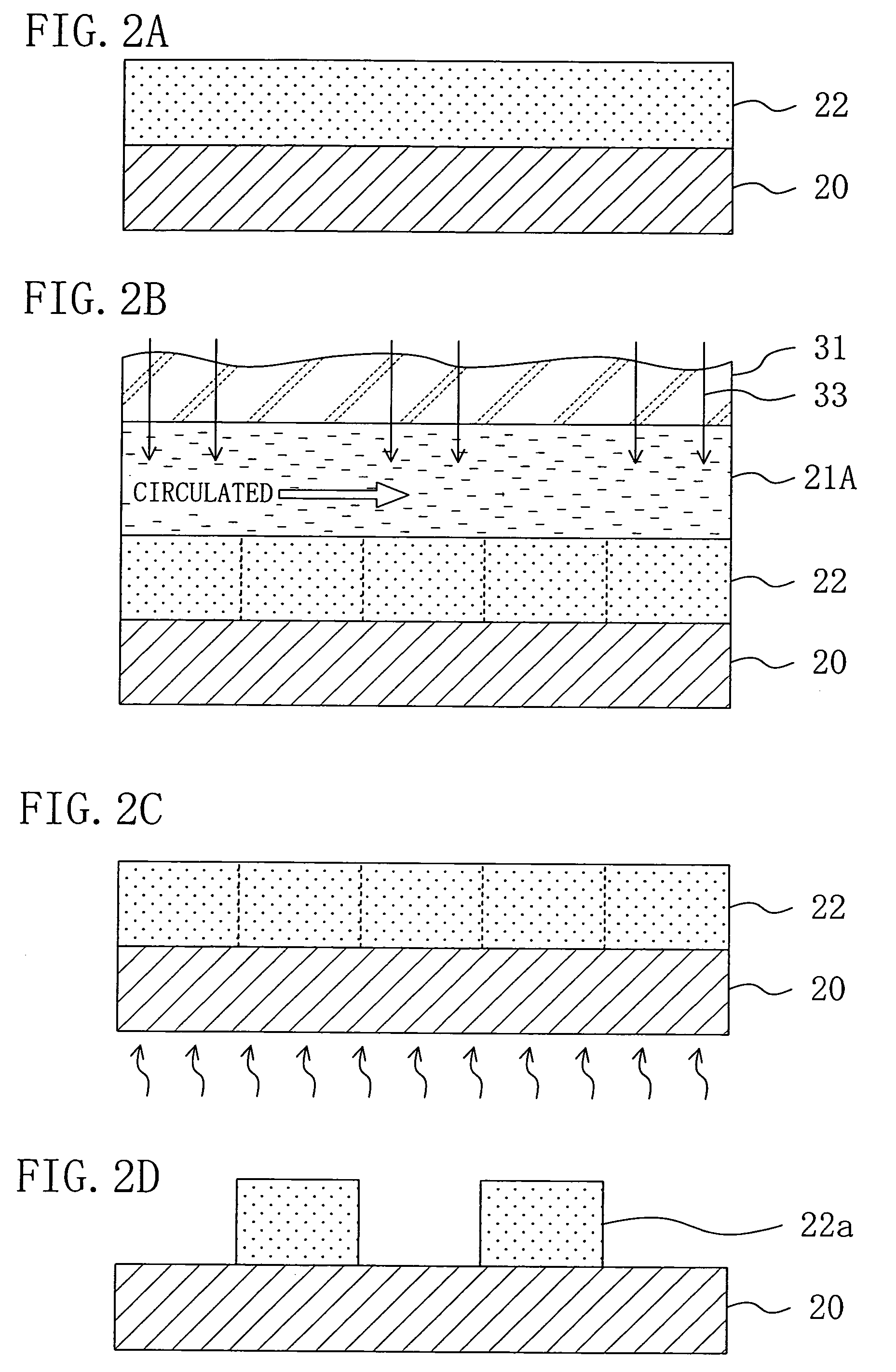
[0054]Now, a pattern formation method using the exposure system shown in FIG. 3 will be described with reference to FIGS. 4A through 4D.

[0055]First, a positive chemically amplified resist material having the following composition is prepared:

[0056]

Base polymer:  2 gpoly((norbornene-5-methy...

embodiment 3

[0061]Embodiment 3 of the invention will now be described with reference to the accompanying drawings.

[0062]FIG. 5 shows a principal portion of an exposure system used for realizing a pattern formation method employing the immersion lithography according to Embodiment 3 of the invention. In FIG. 5, like reference numerals are used to refer to like elements shown in FIG. 3 so as to omit the description.

[0063]As shown in FIG. 5, the exposure system of Embodiment 3 includes a liquid pooling section 45 in the shape of a dip type vessel, and an inlet 45a for allowing an immersion liquid 21C to flow into the liquid pooling section 45 and an outlet 45b for discharging the immersion liquid 21C having flown through the inlet 45a are provided on the side portions of the liquid pooling section 45.

[0064]Now, a pattern formation method using the exposure system shown in FIG. 5 will be described with reference to FIGS. 6A through 6D.

[0065]First, a positive chemically amplified resist material hav...


PUM

PropertyMeasurementUnit
thicknessaaaaaaaaaa
temperatureaaaaaaaaaa
widthaaaaaaaaaa

Abstract

An exposure system includes a liquid supply section for supplying an immersion liquid onto a resist film formed on a substrate; and an exposure section for irradiating the resist film with exposing light through a mask with the immersion liquid provided on the resist film. The liquid supply section includes an immersion liquid tank for circulating the immersion liquid during exposure.

Description

CROSS-REFERENCE TO RELATED APPLICATIONS[0001]This application claims priority under 35 U.S.C. §119 on Patent Application No. 2003-419444 filed in Japan on Dec. 17, 2003, the entire contents of which are hereby incorporated by reference.BACKGROUND OF THE INVENTION[0002]The present invention relates to an exposure system for use in fabrication process and the like for semiconductor devices and a pattern formation method using the exposure system.[0003]In accordance with the increased degree of integration of semiconductor integrated circuits and downsizing of semiconductor devices, there are increasing demands for further rapid development of lithography technique. Currently, pattern formation is carried out through photolithography using exposing light of a mercury lamp, KrF excimer laser, ArF excimer laser or the like, and use of F2 laser lasing at a shorter wavelength is being examined. However, since there remain a large number of problems in exposure systems and resist materials,...

Claims


Application Information

Patent Timeline
Patent Type & Authority Patents(United States)
IPC IPC(8): G03F7/26G03B27/00G03F7/38G03F7/00G03F7/20H01L21/027
CPCG03F7/70341
Inventor ENDO, MASAYUKISASAGO, MASARU
Owner RPX CORP
Why Eureka
Try Eureka