Exposure system and pattern formation method using the same
a technology of pattern formation and exposure system, applied in the field of exposure system, can solve the problems of reducing the productivity and yield of the semiconductor device fabrication process, and achieve the effect of good shape and abnormal exposur
- Summary
- Abstract
- Description
- Claims
- Application Information
AI Technical Summary
Benefits of technology
Problems solved by technology
Method used
Image
Examples
embodiment 1
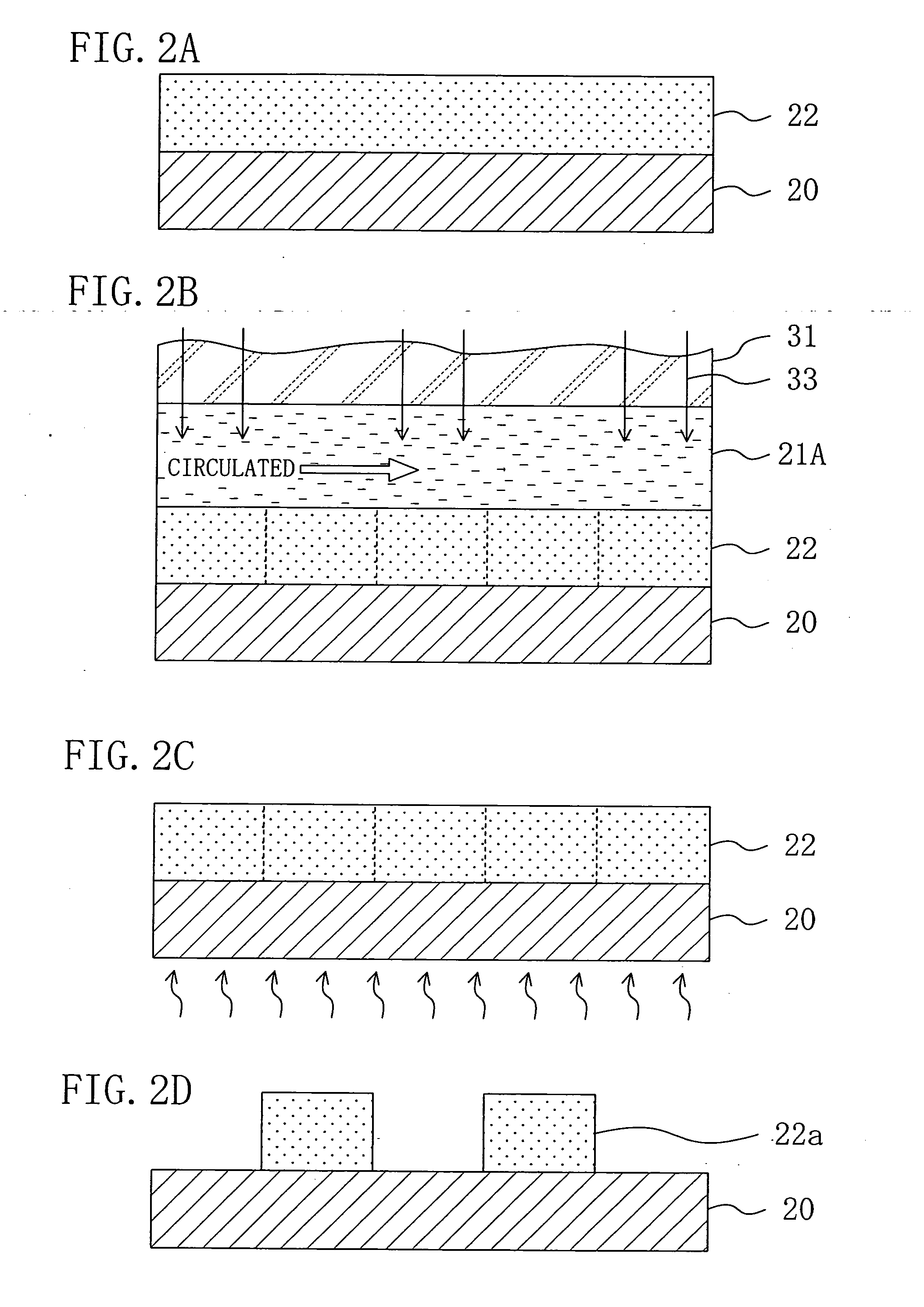
[0038] Embodiment 1 of the invention will now be described with reference to the accompanying drawings.
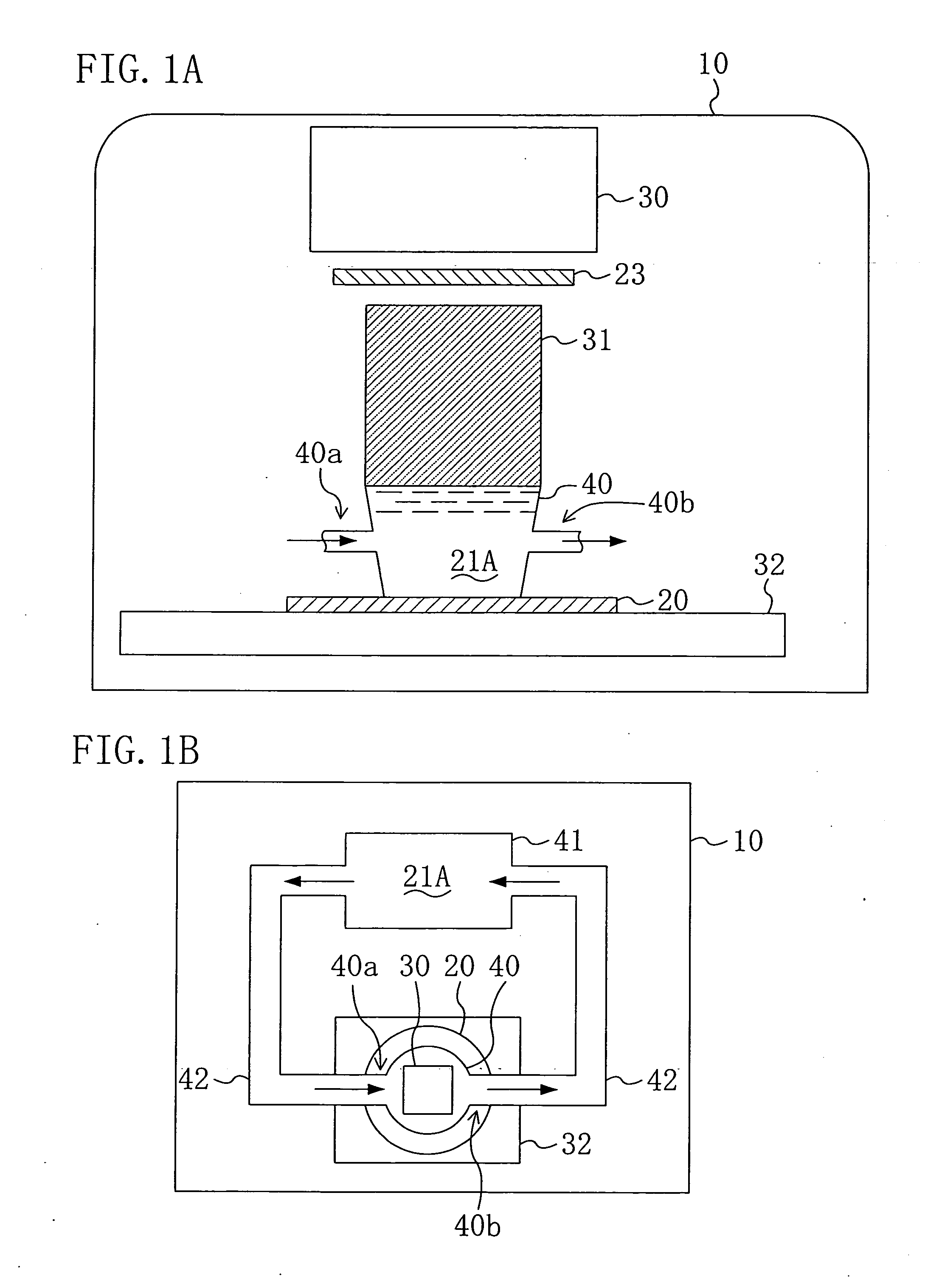
[0039]FIGS. 1A and 1B show a principal portion of an exposure system used for realizing a pattern formation method employing immersion lithography according to Embodiment 1 of the invention, and more specifically, FIG. 1A is a schematic cross-sectional view thereof and FIG. 1B is a schematic plan view thereof.
[0040] As shown in FIG. 1A, the exposure system of Embodiment 1 includes an illumination optical system 30 that is provided within a chamber 10 and works as a light source for exposing a design pattern on a resist film (not shown) applied on a wafer 20, and a bucket type liquid pooling section 40 that supplies an immersion liquid 21A, used for increasing the numerical aperture of exposing light, onto the wafer 20 during the exposure and has an inlet 40a and an outlet 40b.
[0041] Below the illumination optical system 30, a projection lens 31 for projecting the exposing light,...
embodiment 2
[0049] Embodiment 2 of the invention will now be described with reference to the accompanying drawings.
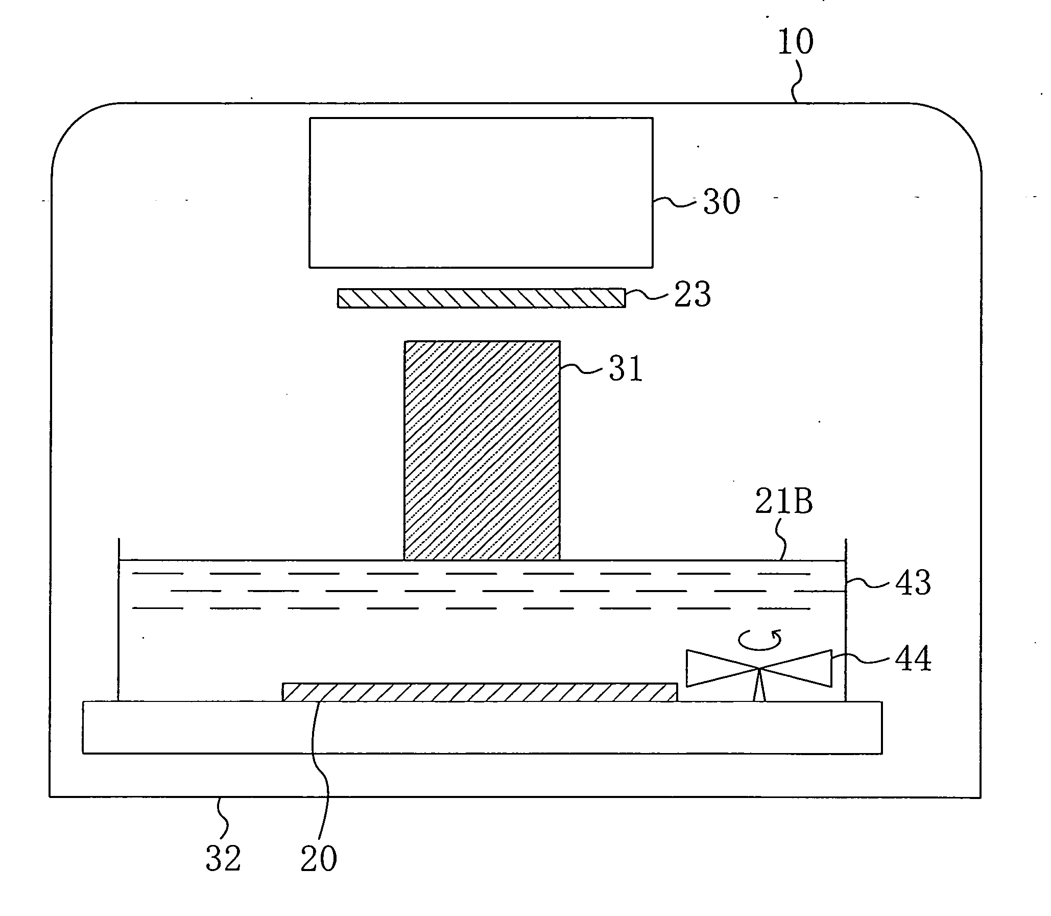
[0050]FIG. 3 shows a principal portion of an exposure system used for realizing a pattern formation method employing the immersion lithography according to Embodiment 2 of the invention. In FIG. 3, like reference numerals are used to refer to like elements shown in FIG. 1A so as to omit the description.
[0051] As shown in FIG. 3, the exposure system of Embodiment 2 includes a liquid pooling section 43 in the shape of a dip type vessel, and on the bottom of the liquid pooling section 43, a stirrer 44 for stirring an immersion liquid 21B pooled therein is provided in a position not disturbing exposure.
[0052] Now, a pattern formation method using the exposure system shown in FIG. 3 will be described with reference to FIGS. 4A through 4D.
[0053] First, a positive chemically amplified resist material having the following composition is prepared:
Base polymer: 2 gpoly((norbornene-5-m...
embodiment 3
[0058] Embodiment 3 of the invention will now be described with reference to the accompanying drawings.
[0059]FIG. 5 shows a principal portion of an exposure system used for realizing a pattern formation method employing the immersion lithography according to Embodiment 3 of the invention. In FIG. 5, like reference numerals are used to refer to like elements shown in FIG. 3 so as to omit the description.
[0060] As shown in FIG. 5, the exposure system of Embodiment 3 includes a liquid pooling section 45 in the shape of a dip type vessel, and an inlet 45a for allowing an immersion liquid 21C to flow into the liquid pooling section 45 and an outlet 45b for discharging the immersion liquid 21C having flown through the inlet 45a are provided on the side portions of the liquid pooling section 45.
[0061] Now, a pattern formation method using the exposure system shown in FIG. 5 will be described with reference to FIGS. 6A through 6D.
[0062] First, a positive chemically amplified resist mate...
PUM
 Abstract
Description
Claims
Application Information
 - R&D
- Intellectual Property
- Life Sciences
- Materials
- Tech Scout
- Unparalleled Data Quality
- Higher Quality Content
- 60% Fewer Hallucinations
Browse by: Latest US Patents, China's latest patents, Technical Efficacy Thesaurus, Application Domain, Technology Topic, Popular Technical Reports.
© 2025 PatSnap. All rights reserved.Legal|Privacy policy|Modern Slavery Act Transparency Statement|Sitemap|About US| Contact US: help@patsnap.com


