

Barrier film material and pattern formation method
a barrier film and film material technology, applied in the direction of photosensitive materials, microlithography exposure apparatus, photomechanical equipment, etc., can solve the problems of reducing the productivity and yield of the fabrication process of a semiconductor device, and the same problems as described abov
- Summary
- Abstract
- Description
- Claims
- Application Information
AI Technical Summary
Benefits of technology
Problems solved by technology
Method used
Image

Examples
embodiment 1
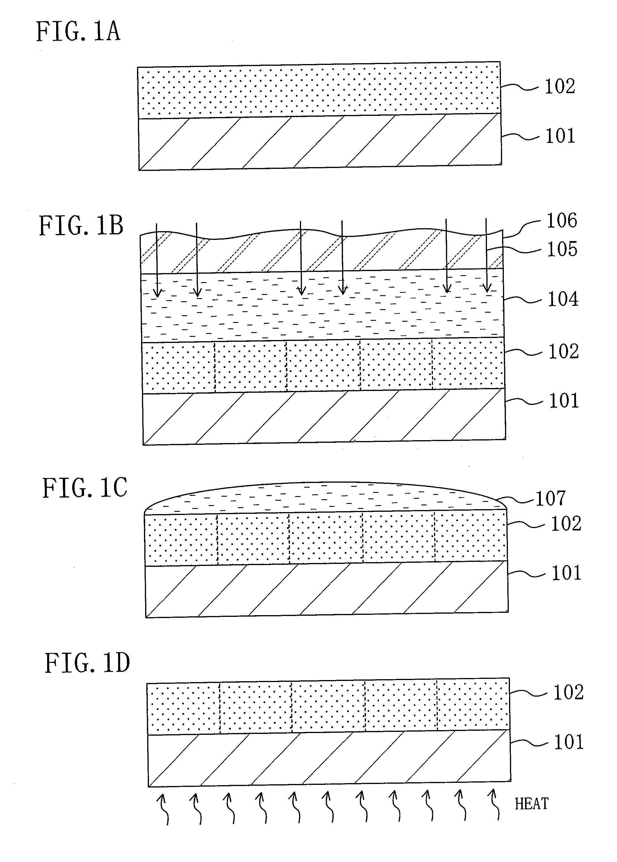
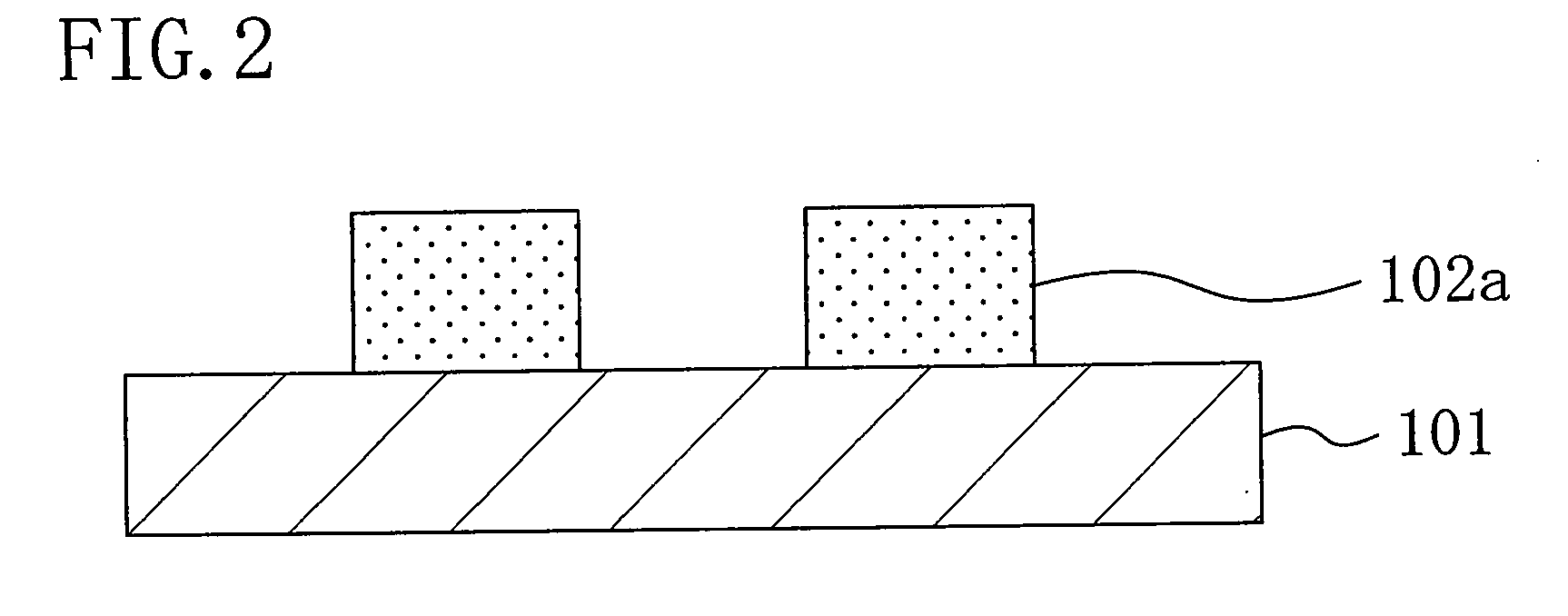
[0054]A pattern formation method using a barrier film material according to a first embodiment of the present invention will be described with reference to FIGS. 1A through 1D and 2.
[0055]First, for example, a positive chemically amplified resist material having the following composition is prepared:
Base polymer: poly((norbornene-5-methylene-t-2gbutylcarboxylate) (50 mol %) - (maleic anhydride)(50 mol %))Acid generator: triphenylsulfonium trifluoromethanesulfonic0.05gacidQuencher: triethanolamine0.002gSolvent: propylene glycol monomethyl ether acetate20g
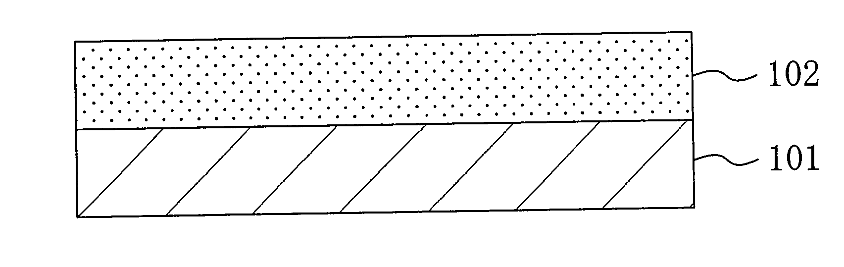
[0056]Next, as shown in FIG. 1A, the aforementioned resist material is applied on a substrate 101 to form a resist film 102 with a thickness of, for example, 0.35 μm.
[0057]Next, as shown in FIG. 1B, with an immersion liquid 104 of water provided between the resist film 102 and a projection lens 106 by, for example, a puddle method, pattern exposure is carried out by irradiating the resist film 102 with exposure light 105, which is Ar...
embodiment 2
[0064]Now, a pattern formation method using a barrier film material according to a second embodiment of the present invention will be described with reference to FIGS. 3A through 3D and 4A through 4C.
[0065]First, a positive chemically amplified resist material having the following composition is prepared:
Base polymer: poly((norbornene-5-methylene-t-2gbutylcarboxylate) (50 mol %) - (maleic anhydride)(50 mol %))Acid generator: triphenylsulfonium trifluoromethanesulfonic0.05gacidQuencher: triethanolamine0.002gSolvent: propylene glycol monomethyl ether acetate20g
[0066]Next, as shown in FIG. 3A, the aforementioned resist material is applied on a substrate 201 to form a resist film 202 with a thickness of 0.35 μm.
[0067]Then, as shown in FIG. 3B, a barrier film 203 which is made of a barrier film material having the following composition and has a thickness of 0.07 μm is formed on the resist film 202 by, for example, spin coating:
Base polymer: polyvinyl hexafluoroisopropyl alcohol 1 gComp...
embodiment 3
[0077]Now, a pattern formation method using a barrier film material according to a third embodiment of the present invention will be described with reference to FIGS. 5A through 5D, 6A, and 6B.
[0078]First, a positive chemically amplified resist material having the following composition is prepared:
Base polymer: poly((norbornene-5-methylene-t-2gbutylcarboxylate) (50 mol %) - (maleic anhydride)(50 mol %))Acid generator: triphenylsulfonium trifluoromethanesulfonic0.05gacidQuencher: triethanolamine0.002gSolvent: propylene glycol monomethyl ether acetate20g
[0079]Next, as shown in FIG. 5A, the aforementioned resist material is applied on a substrate 301 to form a resist film 302 with a thickness of 0.35 μm.
[0080]Then, as shown in FIG. 5B, a barrier film 303 which is made of a barrier film material having the following composition and has a thickness of 0.10 μm is formed on the resist film 302 by, for example, spin coating:
Base polymer: polyacrylic acid1gCompound having acid leaving group:...
PUM
| Property | Measurement | Unit |
|---|---|---|
| size | aaaaa | aaaaa |
| thickness | aaaaa | aaaaa |
| temperature | aaaaa | aaaaa |
Abstract
Description
Claims
Application Information