Method for controlling the microstructure of a laser metal formed hard layer

a technology of laser metal and hard layer, which is applied in the direction of metal-based material coating process, metal-working apparatus, welding/cutting media/materials, etc., can solve the problems of not incorporating the addition of coating material, needing a two-step coating-melting process, and unable to achieve a comparable degree of process control. achieve the effect of enhancing functionality

Active Publication Date: 2010-04-27
ANSALDO ENERGIA IP UK LTD
View PDF38 Cites 24 Cited by
  • Summary
  • Abstract
  • Description
  • Claims
  • Application Information

AI Technical Summary

Benefits of technology

[0013]It is therefore the aim of the present invention to provide a means of creating wear-resistant layer such as coatings or parts of the bulk on the surface of an article having microstructural properties, which can easily be controlled by specifying the most influential process variables such as the melt pool temperature.
[0014]It was found a method of applying a coating a laser metal formed hard layer with a controlled laser metal forming process on the surface of an article according to the principles of the present invention provides one or more of the advantages described herein.
[0015]This enhances the reliability of the manufacturing process and enables the optimisation of the coating microstructure with respect to its wear (or other) behavior. The invention also opens possibilities for creating functionally graded coatings: coatings having different specified properties on various areas of a single component, yet relying on the same hardware and the same coating material. Still, with the inventive method parts of the bulk of the article can be formed.

Problems solved by technology

Some superficially similar patents such as U.S. Pat. No. 4,212,900, U.S. Pat. No. 4,750,947, U.S. Pat. No. 4,015,100 do not utilise the same LMF process, and therefore suffer the disadvantages of necessitating a two step coating-melting process or of not incorporating the addition of coating material as disclosed in U.S. Pat. No. 5,659,479.
Those patents such as U.S. Pat. No. 4,644,127, U.S. Pat. No. 4,981,716, U.S. Pat. No. 5,208,431 or U.S. Pat. No. 5,889,254 utilising the powder and laser beam combination do not aim to monitor the melt condition during the process and are therefore unable to attain a comparable degree of process control.
However if used in this case, a pyrometer signal measured only the bulk workpiece temperature, rather than the melt pool, and spectroscopic measurements of process light were not used to monitor the melt pool temperature.

Method used


Image

  • Method for controlling the microstructure of a laser metal formed hard layer
  • Method for controlling the microstructure of a laser metal formed hard layer
  • Method for controlling the microstructure of a laser metal formed hard layer

Examples


Embodiment Construction

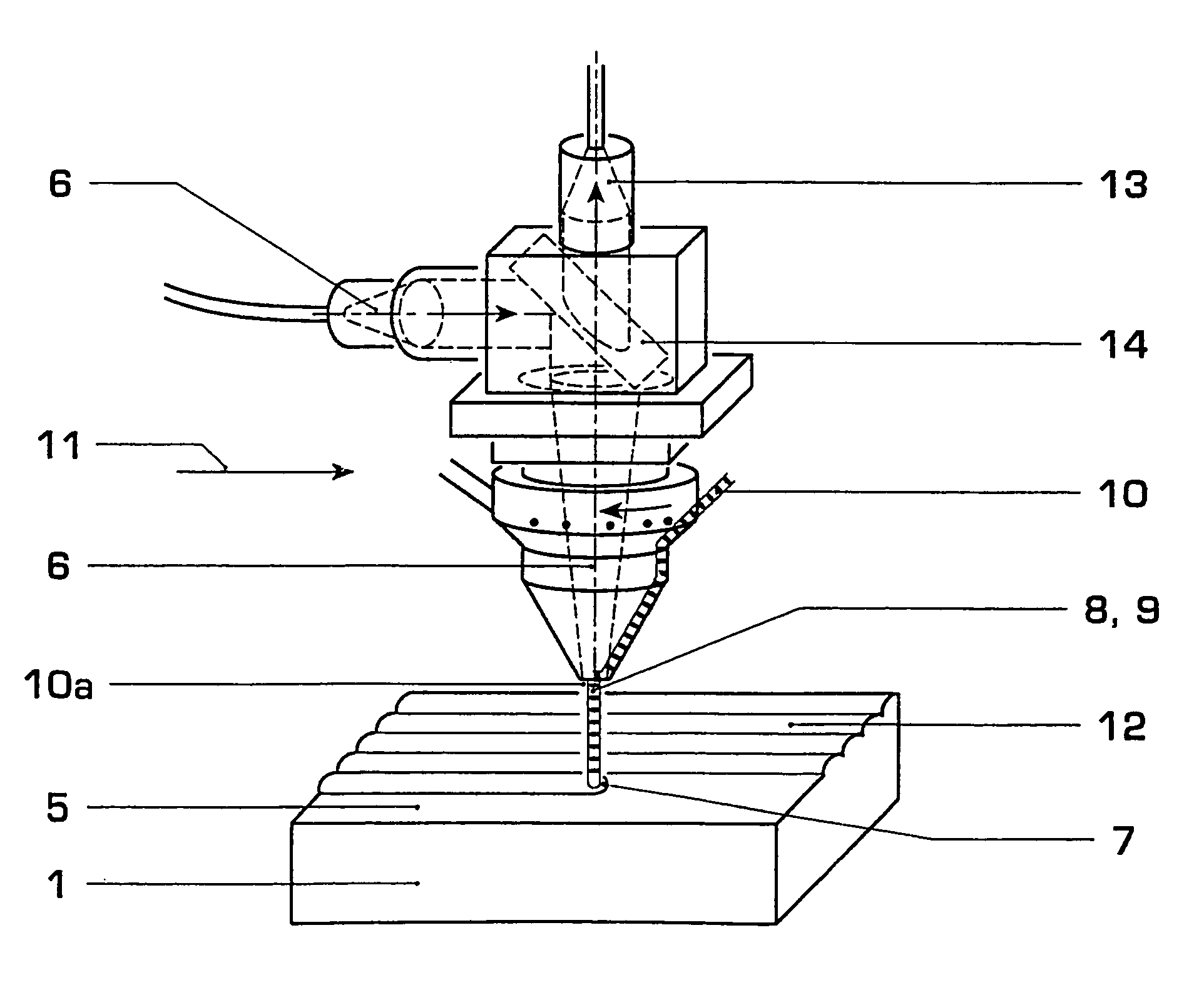
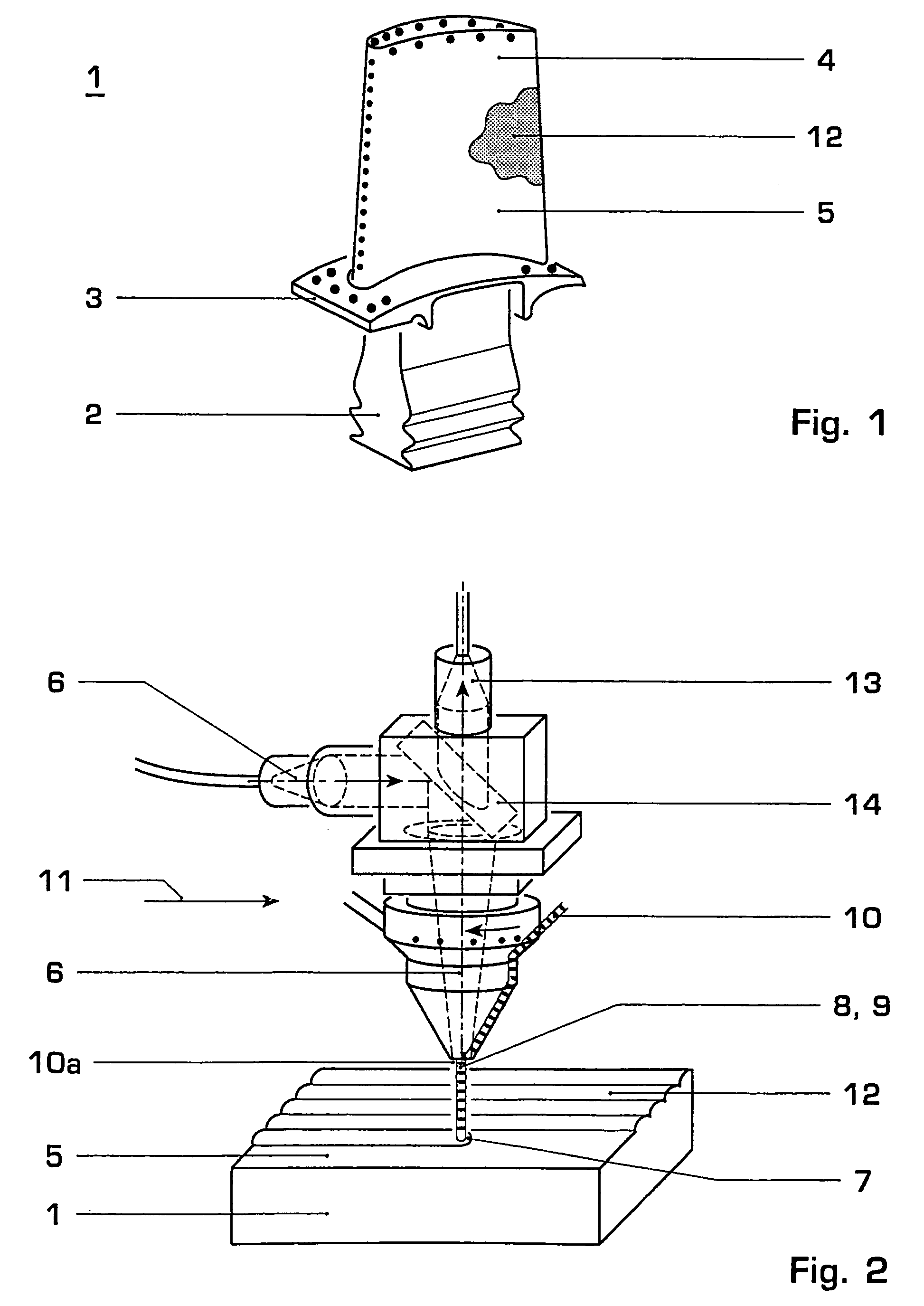
[0034]FIG. 1 shows a single crystal (SX) or directionally solidified (DS) article 1 such as blades or vanes of gas turbine engines, the gas turbine blade comprising a root portion 2, a platform 3 and a blade 4 and having surface 5 with a coating 12. The article 1 can as an example be made from a nickel or cobalt based super alloy. Investment casting methods for producing such SX or DS articles are known e.g. from the prior art U.S. Pat. No. 4,96,501, U.S. Pat. No. 3,690,367 or EP-A1-0 749 790. These articles 1 are normally made from a nickel or cobalt base super alloy. However, for the purpose of the present invention, the article 1 could also be a compressor blade made from steel.

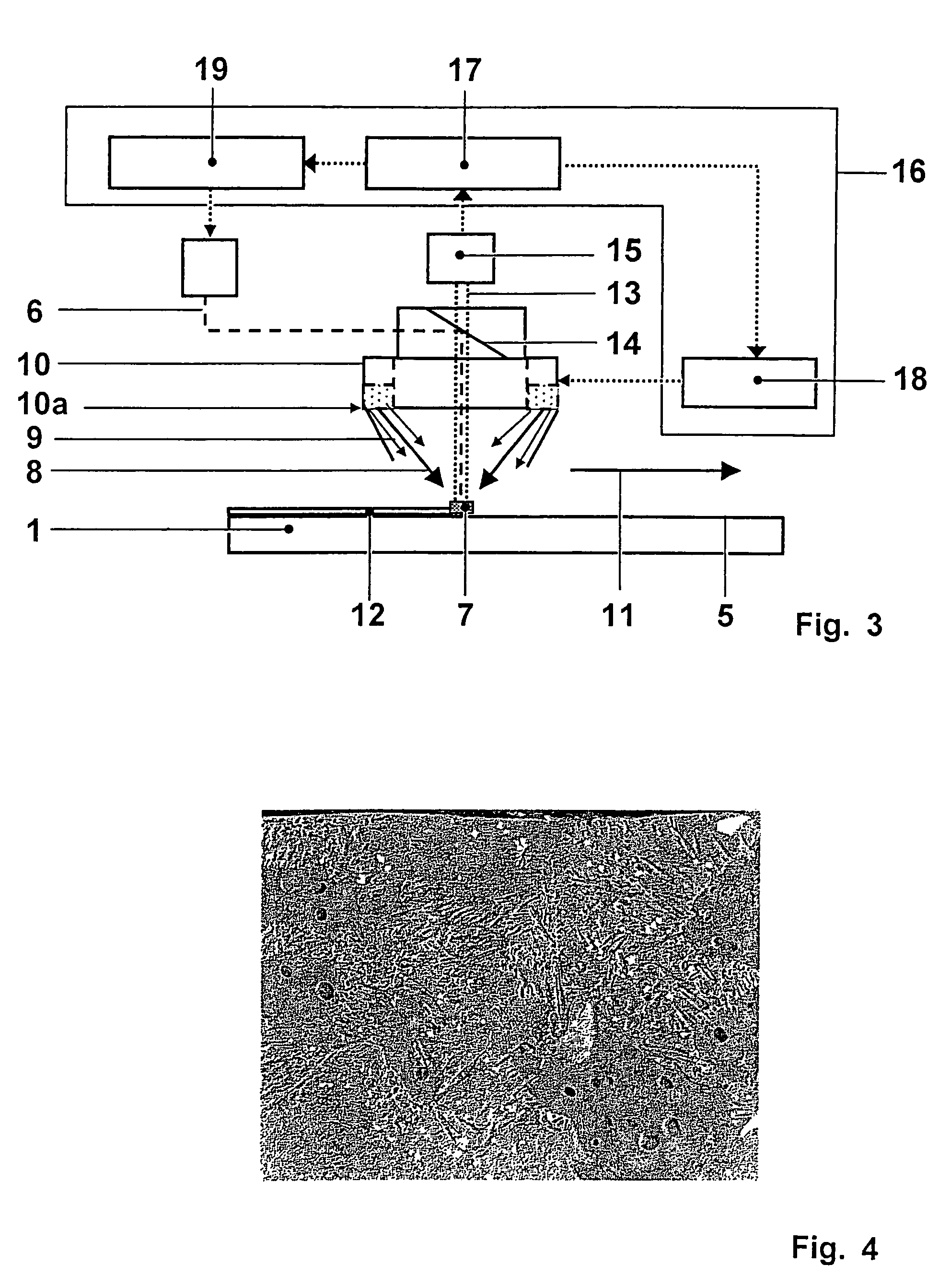
[0035]The herein disclosed method can be used for coating a substrate material of the article 1. This enhances the reliability of the manufacturing process and enables the optimisation of coating microstructure with respect to its wear (or other) behavior. The invention also opens possibilities for creatin...


PUM

PropertyMeasurementUnit
melt pool temperaturesaaaaaaaaaa

Abstract

It is disclosed a method of applying a coating (12) with a controlled laser metal forming process. A light source with a specific power and a signal capturing apparatus is moved over an article (1) to form locally a melt pool (7) on the surface (5) of the article (1) to which a coating powder (8) is injected. An optical signal (13) is captured from the melt pool (7), and the monitored optical signal (13) is used for the determination of the temperature and temperature fluctuations of the melt pool (7). Furthermore, a control system (16) is used to adjust at least one process parameter such as the power of the light source to obtain desired melt pool properties. Subsequently the melt pool (7) solidifies. The high degree of control over the microstructure provides an efficient tool for generating laser metal formed hard coatings (12) with optimised wear properties.

Description

RELATED APPLICATIONS[0001]This application claims priorities under 35 U.S.C. §119 to European Application No. 02405771.3 filed Sep. 6, 2002, and as a Continuation Application Under 35 U.S.C. §120 to PCT Application No. PCT / CH2003 / 000515 filed as an International Application on Jul. 29, 2003 designating the U.S., the entire contents of which are hereby incorporated by reference in their entireties.FIELD OF THE INVENTION[0002]The invention relates to a method of applying a laser metal formed hard layer on the surface of an article with a laser metal forming process allowing for a high degree of control over the microstructure. It provides an efficient tool for generating laser metal formed hard layers with optimised wear properties.BACKGROUND OF THE INVENTION[0003]In the last years laser metal forming (LMF) has been introduced in industrial manufacturing. Laser metal forming is a process where a high power laser locally melts a focussed stream of metal powder or a metal wire onto a su...

Claims


Application Information

Patent Timeline
Patent Type & Authority Patents(United States)
IPC IPC(8): B23K26/00B23K26/34B23K26/03B23K26/14B23K35/32B23K103/04B23K103/08C21D1/09C23C4/12C23C24/10C23C26/00
CPCB23K26/032B23K26/034B23K26/1411B23K35/327C23C4/12C23C24/10B22F2003/1056B22F3/1055B22F5/009C21D1/09B23K26/144B33Y80/00B33Y10/00Y02P10/25B22F12/41B22F10/36B22F12/53B22F10/38B22F10/25B22F12/44B22F12/90
Inventor HOEBEL, MATTHIASOBBARD, EDWARDSCHNELL, ALEXANDER
Owner ANSALDO ENERGIA IP UK LTD
Why Eureka
Try Eureka