High-pressure discharge lamp having electrically conductive transparent coating

a transparent coating and high-pressure discharge technology, which is applied in the direction of gas discharge lamp details, electric discharge tubes, electrical equipment, etc., can solve the negative effect of the optical properties of the headlight system, and achieve the effect of improving the starting capacity

Inactive Publication Date: 2010-04-27
OSRAM GMBH
View PDF15 Cites 6 Cited by
  • Summary
  • Abstract
  • Description
  • Claims
  • Application Information

AI Technical Summary

Benefits of technology

[0003]It is the object of the invention to provide a high-pressure discharge lamp, in particular a mercury-free halogen metal-vapor high-pressure discharge lamp for vehicle headlights having an improved starting capacity.
[0005]The high-pressure discharge lamp according to the invention has a transparent discharge vessel, an ionizable filling which is arranged in the discharge space of the discharge vessel and electrodes, which extend into the discharge space of the discharge vessel, for the purpose of producing a gas discharge, as well as power supply lines, which are passed out of the discharge vessel, for the purpose of supplying energy to the electrodes, the surface of the discharge vessel being provided at least partially with a transparent, electrically conductive coating, with the result that a capacitive coupling is produced between the coating and at least one electrode and / or power supply line. The abovementioned coating forms, together with the at least one electrode and possibly with the associated power supply line, a capacitor, the quartz glass, lying therebetween, of the discharge vessel and the filling gas in the discharge space forming the dielectric of this capacitor. As a result, in particular with the aid of the radiofrequency components of the starting pulse, a dielectrically impeded discharge is produced in the discharge space between the at least one electrode and the coating. This dielectrically impeded discharge generates a sufficient number of free charge carriers in the discharge space to make possible the electrical flashover between the two electrodes of the high-pressure discharge lamp and to markedly reduce the starting voltage required for this purpose. The invention is therefore particularly well suited to mercury-free halogen metal-vapor high-pressure discharge lamps which have an increased starting voltage owing to the absence of mercury.
[0009]In the case of high-pressure discharge lamps which are envisaged for operation in the horizontal position, i.e. with electrodes arranged on a horizontal plane, the transparent, electrically conductive coating is advantageously restricted to a surface region of the discharge vessel which is arranged beneath the electrodes. The coating reflects some of the infrared radiation generated by the discharge back into the discharge space and thus provides for selective heating of the colder regions of the discharge vessel which lie beneath the electrodes and in which the metal halides used for light generation accumulate. As a result, the efficiency of the lamp can be increased without likewise heating the hot regions of the discharge vessel which lie above the electrodes. In addition, the application of the coating only to the colder underside of the discharge vessel reduces the thermal load on the coating, with the result that correspondingly lower demands can be placed on the thermal rating of the coating materials.
[0011]In addition, the lamps according to the invention in groups 3 and 4 also have another advantage over the uncoated lamps in groups 1 and 2. As can be seen from FIG. 7, the lamps according to the invention in groups 3 and 4 have a higher operating voltage than the uncoated lamps in groups 1 and 2. As a result, with the lamps according to the invention a correspondingly lower lamp current is required during lamp operation in order to reach the desired power rating of 35 watts. Correspondingly, the operating devices can be dimensioned for lower current levels.
[0014]The intermediate space between the outer bulb and the discharge vessel is advantageously provided with a gas filling which has a coldfilling pressure in the range from 5 kPa to 150 kPa. In this case, coldfilling pressure means the filling pressure measured at a temperature of the gas filling of 22 degrees Celsius. Owing to the gas filling, gaseous impurities, such as water vapor and carbon dioxide as well as combustion gases which have formed during sealing of the lamp vessel, and the temperature gradient along the discharge vessel are reduced.
[0015]The abovementioned gas filling advantageously contains inert gases which do not undergo any chemical reaction with the material of the coating according to the invention on the discharge vessel. The gas filling therefore preferably contains nitrogen or at least one noble gas. In addition, the gas filling advantageously contains small amounts of oxygen in order to counteract diffusion of oxygen from the coating which is preferably formed as a doped tin oxide layer or ITO layer on the discharge vessel.

Problems solved by technology

In the case of a resistance below 103 ohms / cm, the layer thickness is so great that it can have a negative effect on the optical properties of the headlight system owing to light reflection.

Method used


Image

  • High-pressure discharge lamp having electrically conductive transparent coating
  • High-pressure discharge lamp having electrically conductive transparent coating
  • High-pressure discharge lamp having electrically conductive transparent coating

Examples


Embodiment Construction

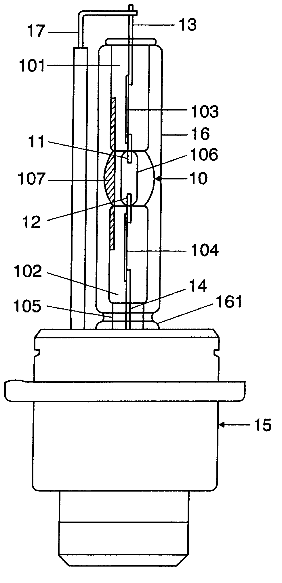
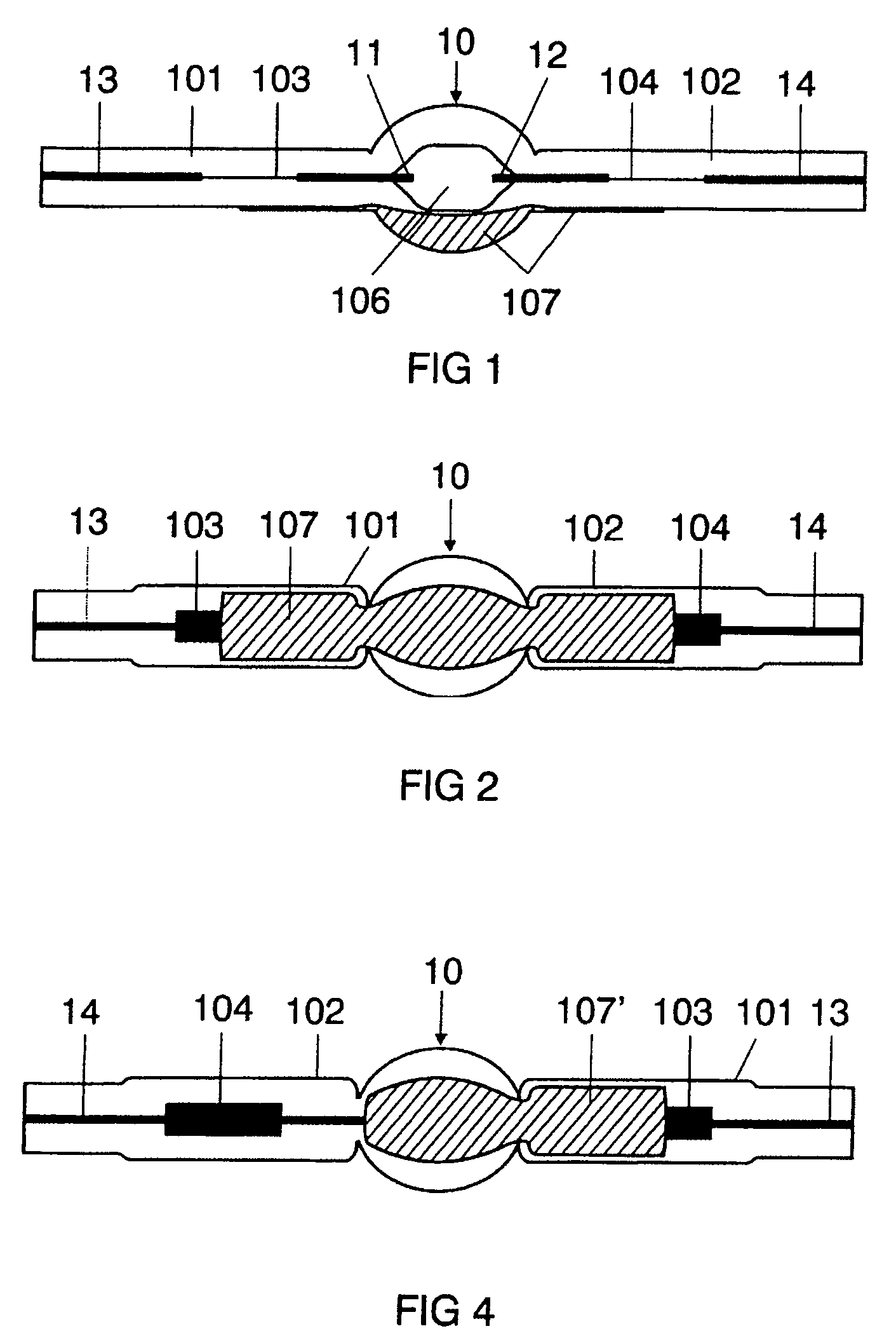
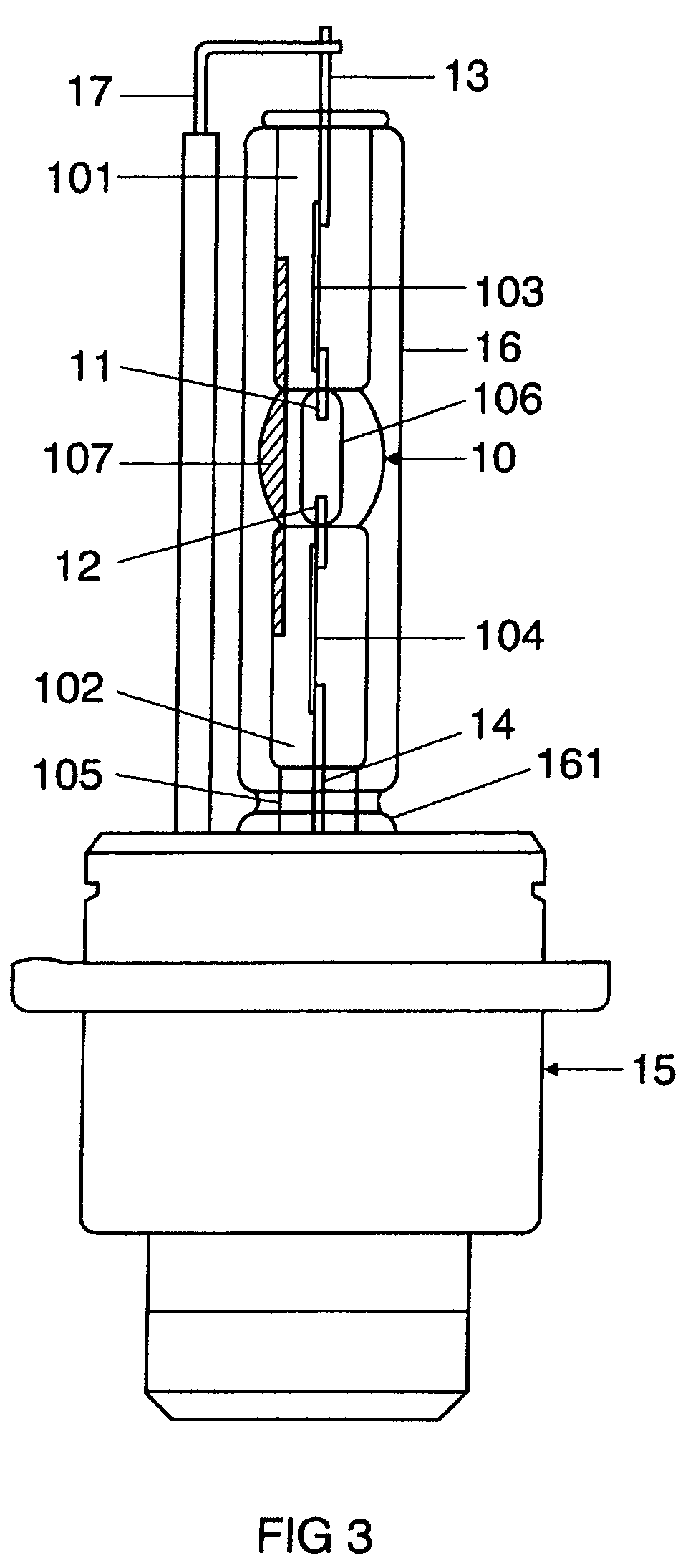
[0024]The preferred exemplary embodiment of the invention illustrated schematically in FIG. 3 is a mercury-free halogen metal-vapor high-pressure discharge lamp having an electrical power consumption of approximately 35 watts. This lamp is envisaged for use in a vehicle headlight. It has a discharge vessel 30 made from quartz glass which is sealed at two ends and has a volume of 24 mm3, in which an ionizable filling, comprising xenon and halides of the metals sodium, scandium, zinc and indium, is enclosed in a gas-tight manner. In the region of the discharge vessel 106, the inner contour of the discharge vessel 10 is circular-cylindrical, and its outer contour is ellipsoidal. The internal diameter of the discharge space 106 is 2.6 mm and its external diameter is 6.3 mm. The two ends 101, 102 of the discharge vessel 10 are each sealed by means of a fused molybdenum foil seal 103, 104. Located in the interior of the discharge vessel 10 are two electrodes 11, 12, between which the disc...


PUM


Abstract

The invention relates to a high-pressure discharge lamp having a transparent discharge vessel, an ionizable filling which is arranged in the discharge space of the discharge vessel and electrodes, which extend into the discharge space of the discharge vessel, for the purpose of producing a gas discharge, as well as power supply lines, which are passed out of the discharge vessel, for the purpose of supplying energy to the electrodes, the discharge vessel of the high-pressure discharge lamp being provided partially with an electrically conductive coating, with the result that a capacitive coupling is produced between the coating and at least one electrode and / or power supply line. As a result, the starting properties and the luminous efficiency of the lamp are improved.

Description

I. TECHNICAL FIELD[0001]The invention relates to a high-pressure discharge lamp having a transparent discharge vessel, an ionizable filling which is arranged in the discharge space of the discharge vessel and electrodes, which extend into the discharge space of the discharge vessel, for the purpose of producing a gas discharge, as well as power supply lines, which are passed out of the discharge vessel, for the purpose of supplying energy to the electrodes, the high-pressure discharge lamp having an electrically conductive, transparent layer.II. BACKGROUND ART[0002]Such a high-pressure discharge lamp has been disclosed, for example, in the European patent specification EP 0 991 107 B1. On page 4, at lines 12 to 26 of column 6 of this patent specification, a high-pressure discharge lamp with a base at one end for a motor vehicle headlight is described which has a discharge vessel surrounded by a vitreous outer bulb, the outer bulb being provided with a transparent, electrically condu...

Claims


Application Information

Patent Timeline
Patent Type & Authority Patents(United States)
IPC IPC(8): H01J17/16
CPCH01J61/547H01J61/35H01J61/073
Inventor BEDYNEK, FLORIANBONIGK, MICHAELGRUNDMANN, DIRKREINERS, THOMASSCHIMKE, CONRAD
Owner OSRAM GMBH
Why Eureka
Try Eureka