
Polishing apparatus and method of reconditioning polishing pad

a polishing pad and apparatus technology, applied in the field of polishing apparatus and reconditioning polishing pads, can solve the problems of dulling of abrasive grains fixed to the bottom surface of the dresser, reducing the cutting capacity of the polishing pad, and affecting the operation so as to reduce the downtime improve the efficiency of the cmp apparatus

Active Publication Date: 2010-05-04
HEFEI RELIANCE MEMORY LTD
View PDF14 Cites 12 Cited by
  • Summary
  • Abstract
  • Description
  • Claims
  • Application Information

AI Technical Summary

Benefits of technology

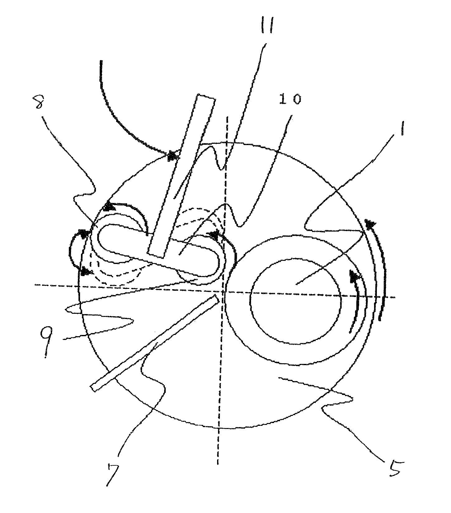
The present invention aims to improve the throughput of a CMP apparatus and reduce its downtime. The polishing apparatus of the invention supports at least two dressed and includes a dresser oscillator that causes the dressed to oscillate simultaneously on the polishing pad. This shortens the polishing pad cutting time and suppresses a decrease in the throughput of the CMP apparatus when the polishing pad diameter increases to match an increase in the wafer diameter. It is preferred that at least two dressed be simultaneously moved onto the polishing pad, that each of the dressed be caused to rotate on its own axis, and that the dressed be caused to oscillate simultaneously on the polishing pad. The technique disclosed in Japanese laid-open patent publication No. 11-48122 is not a technique by which two dressed are used for the polishing pad before and after polishing or during polishing.

Problems solved by technology

However, conventional CMP apparatus have had the following problems.
Also, when a dresser is used, the edge of diamond abrasive grains fixed to a bottom surface of the dresser becomes dull and the cutting capacity of the polishing pad decreases.
When the polishing pad diameter increases, the cutting time becomes long and, therefore, the cumulative number of treated wafers per dresser decreases.

Method used


Image

  • Polishing apparatus and method of reconditioning polishing pad
  • Polishing apparatus and method of reconditioning polishing pad
  • Polishing apparatus and method of reconditioning polishing pad

Examples


Embodiment Construction

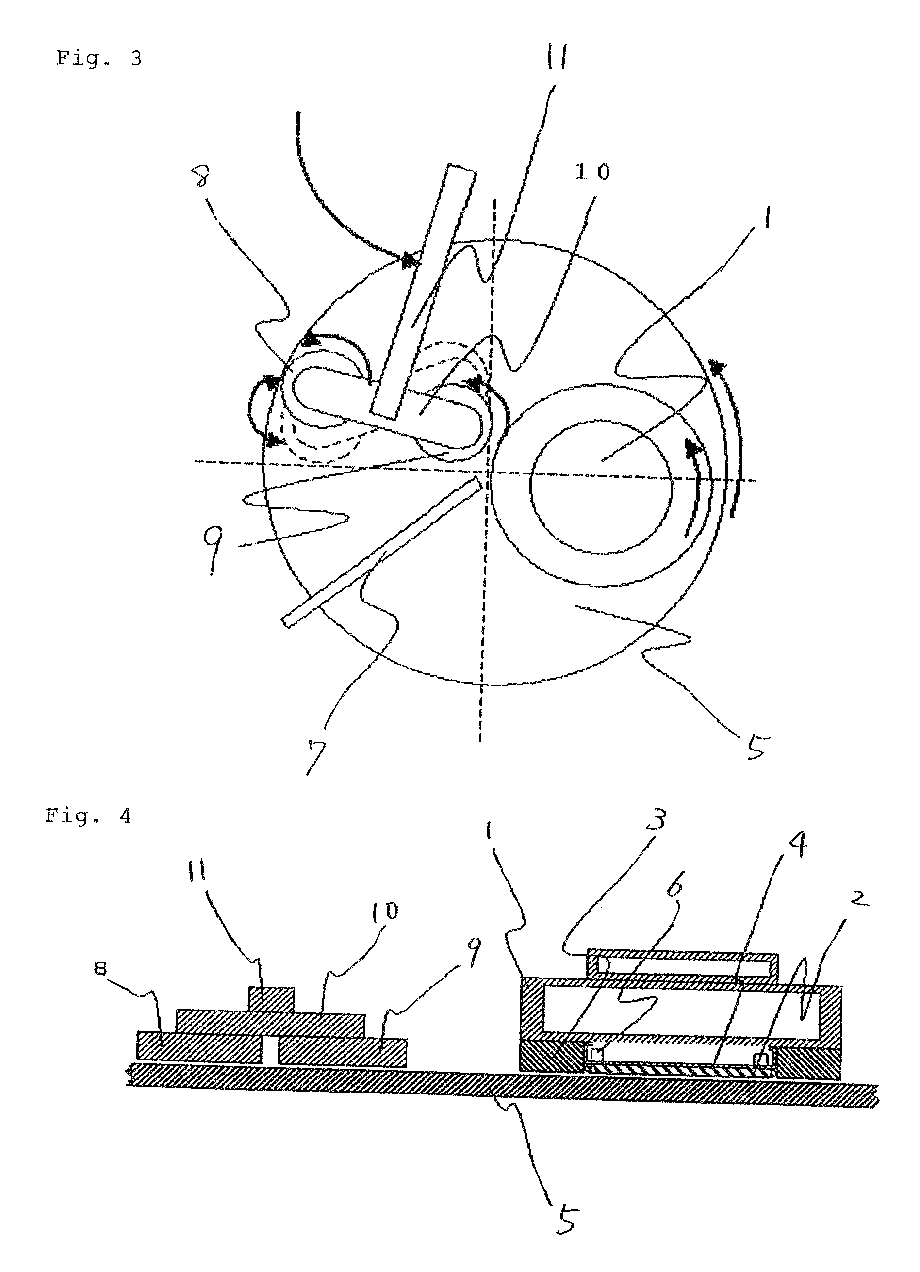
[0028]FIG. 3 is a plan view of an oxide film CMP apparatus showing mainly a polishing head and a dresser in an exemplary embodiment of the present invention, and FIG. 4 shows a sectional view of the apparatus of FIG. 3. Incidentally, in these figures, parts having the same functions as parts of the CMP apparatus of the related art are identified by the same reference numerals as shown in FIGS. 1 and 2.

[0029]As shown in FIGS. 3 and 4, the CMP apparatus of this exemplary embodiment has polishing head 1, polishing pad 5, and at least two dressers 8, 9.

[0030]Polishing head 1 arranged on polishing pad 5 is formed from a metal casing, and retainer ring 3 made of polyphenylene sulfide (hereinafter abbreviated as PPS) or polyetheretherketone (hereinafter abbreviated as PEEK) is attached to the periphery of a bottom surface of polishing head 1. On the inner side of retainer ring 3 on the bottom surface of polishing head 1, there are disposed membrane 4 made of neoprene rubber, which correspo...


PUM

PropertyMeasurementUnit
pressureaaaaaaaaaa
radiusaaaaaaaaaa
sizeaaaaaaaaaa

Abstract

This polishing apparatus includes a head that holds a semiconductor wafer, a polishing pad that polishes a surface to be polished of the semiconductor wafer held by the head, and a dresser that reconditions the polishing pad by cutting the polishing pad. The polishing apparatus polishes a surface to be polished of the semiconductor wafer while causing the head and the polishing pad to rotate and reconditions the polishing pad by use of the dresser before and after polishing the surface to be polished. The polishing apparatus of the present invention supports at least two dressers so that the dressers can rotate on their own axes and further includes a dresser oscillator that causes the dressers to oscillate simultaneously on the polishing pad.

Description

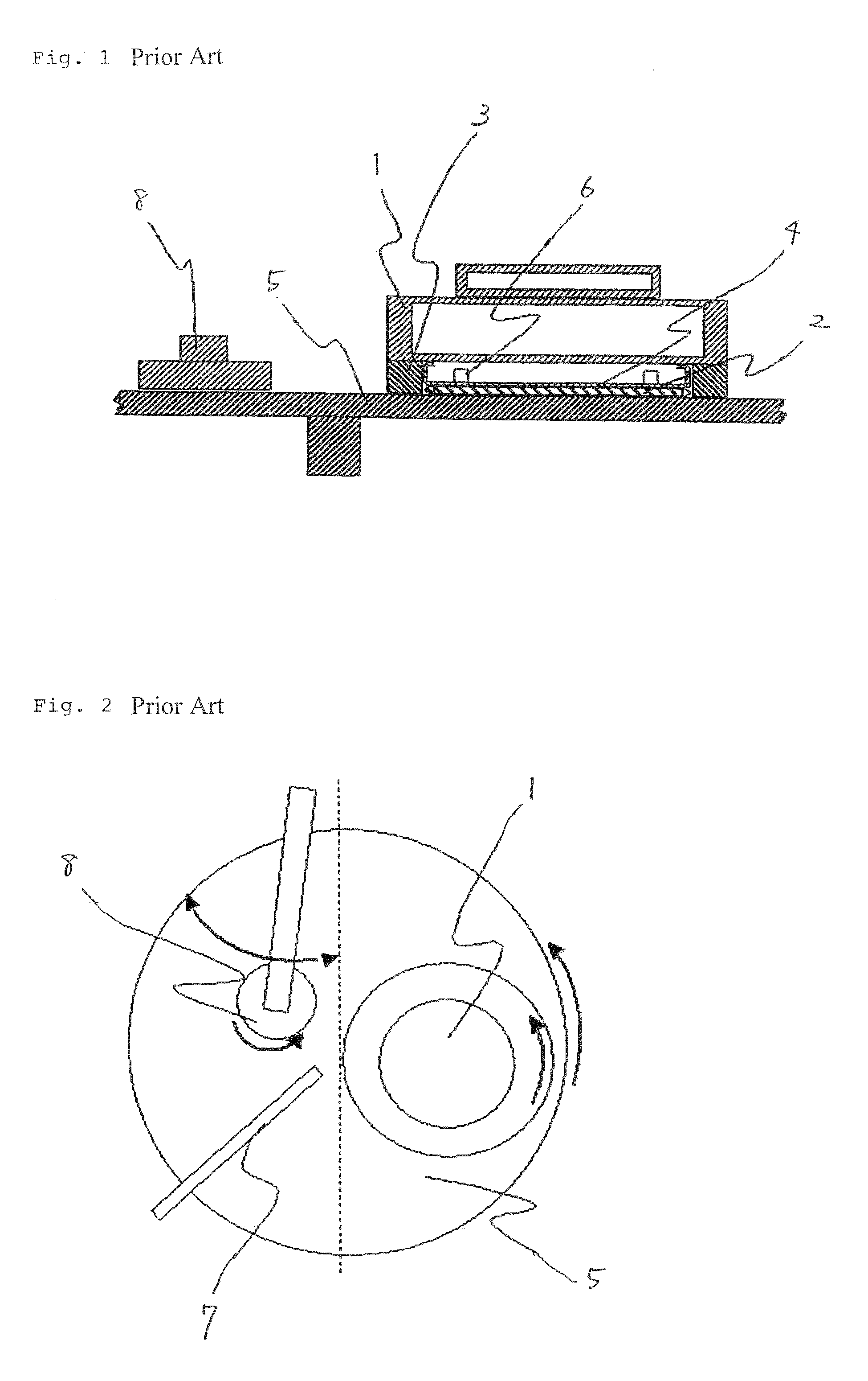
[0001]This application is based upon and claims the benefit of priority from Japanese patent application No. 2007-094472, filed on Mar. 30, 2007, the disclosure of which is incorporated herein in its entirety by reference.BACKGROUND OF THE INVENTION[0002]1. Field of the Invention[0003]The present invention relates to a CMP (chemical mechanical polishing) apparatus that polishes wafers in the manufacturing process of semiconductor devices, and a dresser that reconditions a polishing pad provided in a CMP apparatus.[0004]2. Description of the Related Art[0005]The surface of a polishing pad is worn down during wafer polishing in the CMP process and, therefore, it is inevitable to perform reconditioning by the use of a dresser. Under the present circumstances, one dresser is arranged for one polishing pad and reconditioning is performed by causing the polishing pad and the dresser to rotate on their own axes.[0006]FIG. 1 is a sectional view of a CMP apparatus of a related art in which o...

Claims


Application Information

Patent Timeline
Patent Type & Authority Patents(United States)
IPC IPC(8): B24B1/00B24B53/017B24B53/02H01L21/304
CPCB24B53/017B24B47/00
Inventor SAITO, TOSHIYA
Owner HEFEI RELIANCE MEMORY LTD
Learn More