
Contact element and a contact arrangement

a contact element and contact arrangement technology, applied in the direction of coupling contact members, coupling device connections, contacts, etc., can solve the problems of surface damage, poor electric conductivity of solid lubricants, and often worn away

Active Publication Date: 2010-05-04
ABB RES LTD +1
View PDF29 Cites 7 Cited by
  • Summary
  • Abstract
  • Description
  • Claims
  • Application Information

AI Technical Summary

Benefits of technology

"The present invention provides an improved electric contact element by improving the contact layer with a nanocomposite film. The film comprises a matrix of amorphous carbon and crystallites of metal carbide embedded therein. The matrix has properties that make it suitable for various uses of the contact element. The film has a low resistivity and excellent wear resistance. The film can be deposited using vapor deposition techniques and has a high ratio of sp2 / sp3 bonds between carbon atoms, which makes it more graphite-like and improves its adaptivity to the surface of the contact member. The film can also contain a solid solution of a weak or non-carbide forming metal. The addition of a third metal in the matrix can further improve the properties of the contact layer. The film has a thickness of 0.05-10 μm and can be deposited using vapor deposition techniques or solution methods."

Problems solved by technology

However, it has turned out that the metals used until now for such a contact layer have shown a tendency to get stuck to the surface on the contact member bearing thereagainst, which may result in damaging the surface near portions of the contact element and / or contact member, when traction forces attempt to move the contact element with respect to the contact member, for instance as a consequence of a difference in coefficient of thermal expansion of the material of the contact element and that of the contact member upon temperature changes or when the contact element and the contact member are to be moved with respect to each other in a sliding contact.
However, solid lubricants have a poor electric conductivity and are often worn away when the contact surfaces are sliding against each other.

Method used


Image

  • Contact element and a contact arrangement
  • Contact element and a contact arrangement
  • Contact element and a contact arrangement

Examples


Embodiment Construction

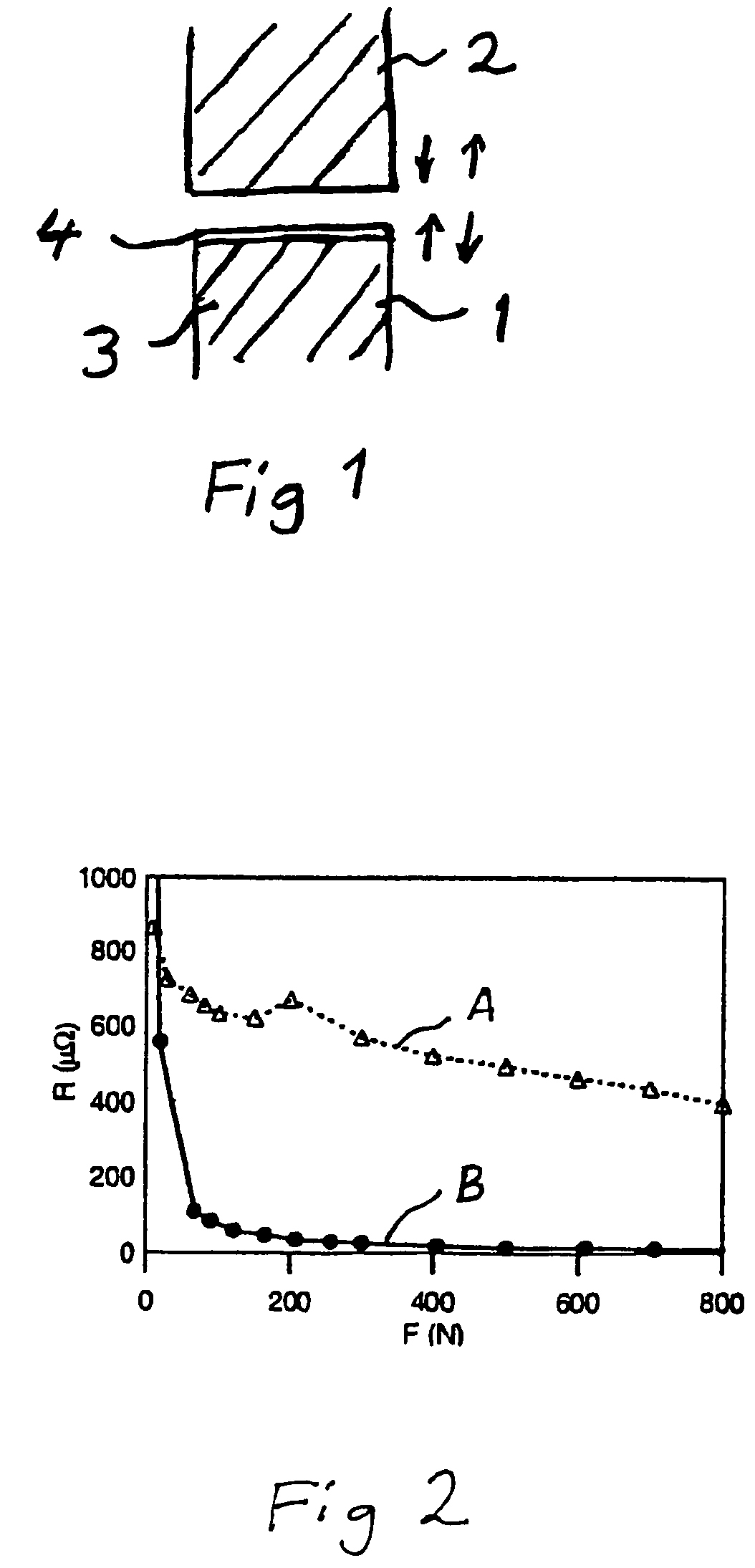
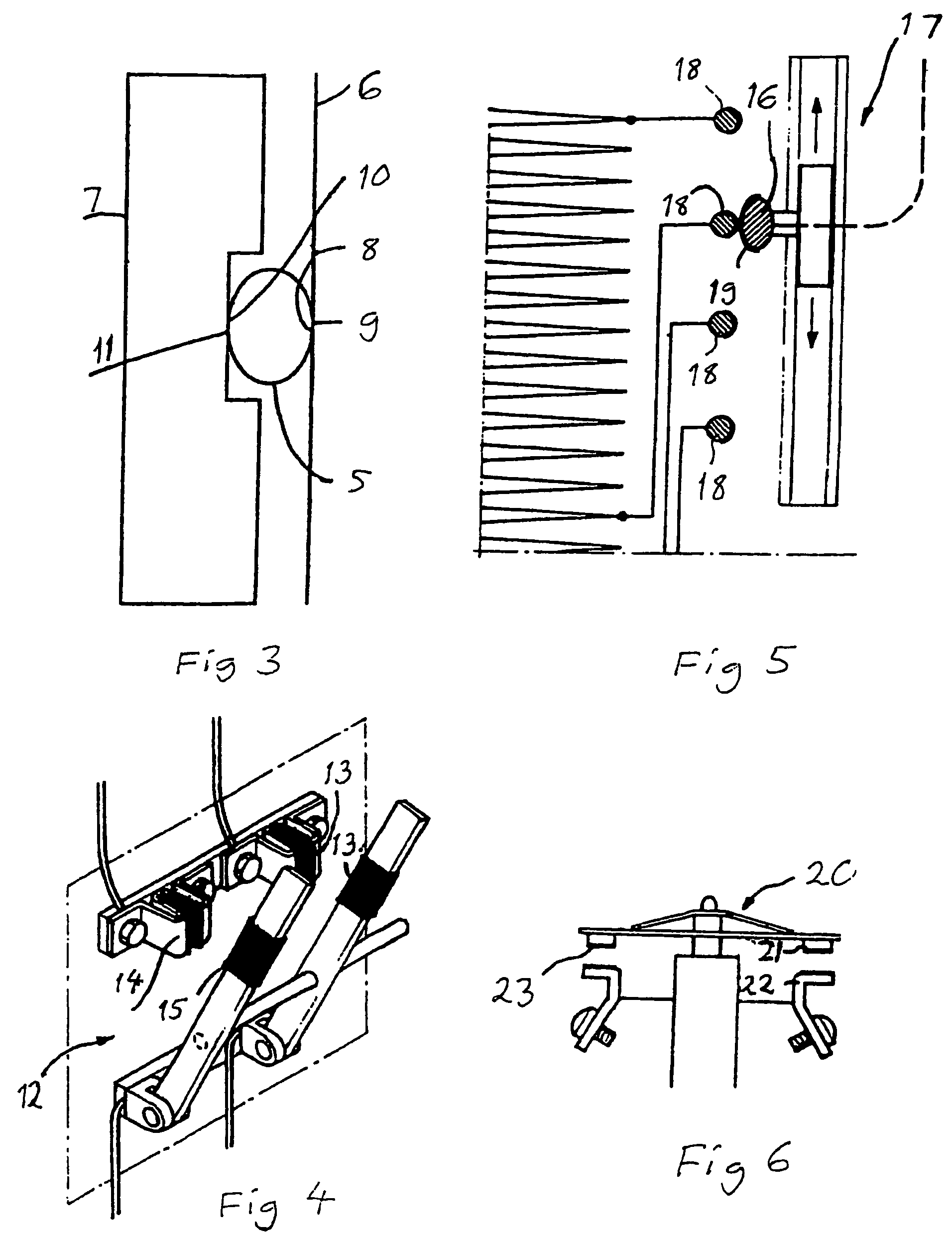
[0035]A contact element 1 forming an electric contact to a contact member 2 for enabling an electric current to flow between said contact element and said contact member is very schematically shown in FIG. 1. The contact element comprises a body 3, which may be for instance of aluminium or copper, and has at least one contact surface thereof coated with a contact layer 4 to be applied against said contact member. The contact layer 4 has typically a thickness of 0.05-10 μm, so that the thickness shown in FIG. 1 is exaggerated with respect to other dimensions of the contact element and the contact member for illustrating purposes.

[0036]The contact layer 4 comprises a nanocomposite film having a matrix of amorphous carbon and crystallites of nano-size, i.e. with dimensions in the range of 1-100 nm, of at least one metal carbide embedded therein. This gives the contact layer the excellent properties reported above. The metal is preferably a transition metal. The hybridization of the amo...


PUM


Abstract

A contact element for making an electric contact to a contact member for enabling an electric current to flow between the contact element and the contact member includes a body having at least one contact surface thereof coated with a contact layer to be applied against the contact member. The contact layer includes a nanocomposite film having a matrix of amorphous carbon and crystallites of nano-size, i.e. with dimensions in the range of 1-100 nm, of at least one metal carbide embedded therein.

Description

CROSS-REFERENCE TO RELATED APPLICATIONS[0001]This application claims priority to U.S. provisional patent application 60 / 796,521 filed 2 May 2006 and Swedish patent application 0501667-0 filed 12 Jul. 2005 and is the national phase under 35 U.S.C. §371 of PCT / SE2006 / 000769.TECHNICAL FIELD OF THE INVENTION AND PRIOR ART[0002]The present invention relates to a contact element for making an electric contact to a contact member for enabling an electric current to flow between said contact element and said contact member, said contact element comprising a body having at least one contact surface thereof coated with a contact layer to be applied against said contact member, as well as a sliding electric contact arrangement, i.e. a contact arrangement in which two contact surfaces adapted to be applied against each other for establishing an electric contact may slide with respect to each other when establishing and / or interrupting and / or maintaining the contact action.[0003]Such a contact e...

Claims


Application Information

Patent Timeline
Patent Type & Authority Patents(United States)
IPC IPC(8): H01H1/02
CPCH01H1/027H01L24/72H01R13/03H01L2924/01047H01H9/0016H01H2300/036H01L2924/01013H01L2924/01029H01L2924/01078H01L2924/01082H01L2924/01005H01L2924/01006H01L2924/01019H01L2924/01033H01L2924/01041H01H1/36B82Y30/00H01H1/021
Inventor LEWIN, ERIKJANSSON, ULFWILHELMSSON, OLA
Owner ABB RES LTD
Learn More