Sensor system for machine tools

a sensor system and machine tool technology, applied in the field of sensor systems, can solve the problems of inability to supply energy to the measuring instrument, inconvenient energy supply via cable, and the monitoring tool along with the measurement instrument must stay, so as to achieve continuous and stable measurement operation of the sensor, reduce the cost of battery exchange, and reduce the effect of maintenance costs

Inactive Publication Date: 2010-05-04
ARTIS GES FUR ANGEWANDTE MESSTECHN +1
View PDF12 Cites 24 Cited by
  • Summary
  • Abstract
  • Description
  • Claims
  • Application Information

AI Technical Summary

Benefits of technology

[0009]In contrast to the sensor systems of the prior art mentioned above, the provision of two energy supply units according to the present invention allows that the at least one measurement instrument of a sensor also works reliably within work spaces of the machine tool, in which the surrounding electromagnetic field is weak or even non-existent; this is since in these situations the second energy supply unit, which is based on the battery, takes over the energy supply of the measurement instruments of the sensor. Thus the provision of two energy supply units according to the present invention makes possible an essentially continuous and stable measurement operation of the sensor such that also critical situations like deep bore holes or millings can be reliably monitored.
[0010]The provision of the first energy supply unit in addition to the second battery-supported supply unit makes sure that the batteries have not to be frequently exchanged or loaded. Since the second energy supply unit is only used in some machining configurations, the lifetime of the battery is considerably increased.

Problems solved by technology

A problem is posed by the energy supply of the measuring instrument.
An energy supply via cable is unsuitable, if the measuring instrument is mounted on a fast moving part of the machine tool like a tool spindle.
However, the energy supply systems which are proposed in the above-mentioned documents DE 101 63 734 A1 and DE 199 26 799 A1 have the disadvantages that the monitored tool along with the measurement instrument has to stay always in a region in which there is a sufficiently strong electromagnetic field.
If the spindle of the machine tool has a large working range or the electromagnetic field is shielded by the work piece being machined, since e.g. deep drillings are performed, possibly a sufficiently strong external field is not present in the entire work space.
In particular, the monitoring of deep borings or millings is especially important, since in this case the risk of damages for the used tools is especially high.
If one wants to sufficiently increase the external field strength within the entire working space, in order to compensate for shielding effects, this is very costly, since a multitude of primary coils is needed and the generation of strong fields necessitates the use of large quantities of energy.
Further, the installation of one or more primary coils within the work space possibly restricts the mobility of components of the machine tool.

Method used


Image

  • Sensor system for machine tools
  • Sensor system for machine tools
  • Sensor system for machine tools

Examples


Embodiment Construction

[0021]In the following, presently preferred embodiments of the sensor system according to the invention will be described in more detail. Thereby, the sensor system according to the present invention will be described in the context of a cutting machine tool with tool spindle. However, employing the sensor system according to the invention in other machines is equally possible.

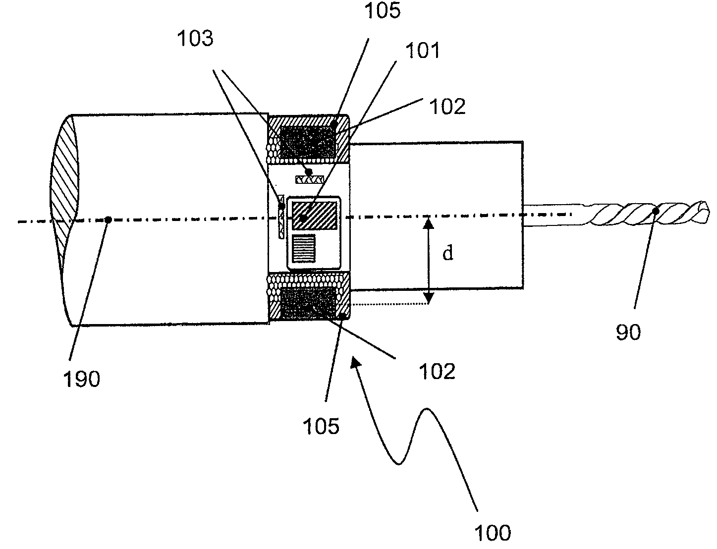
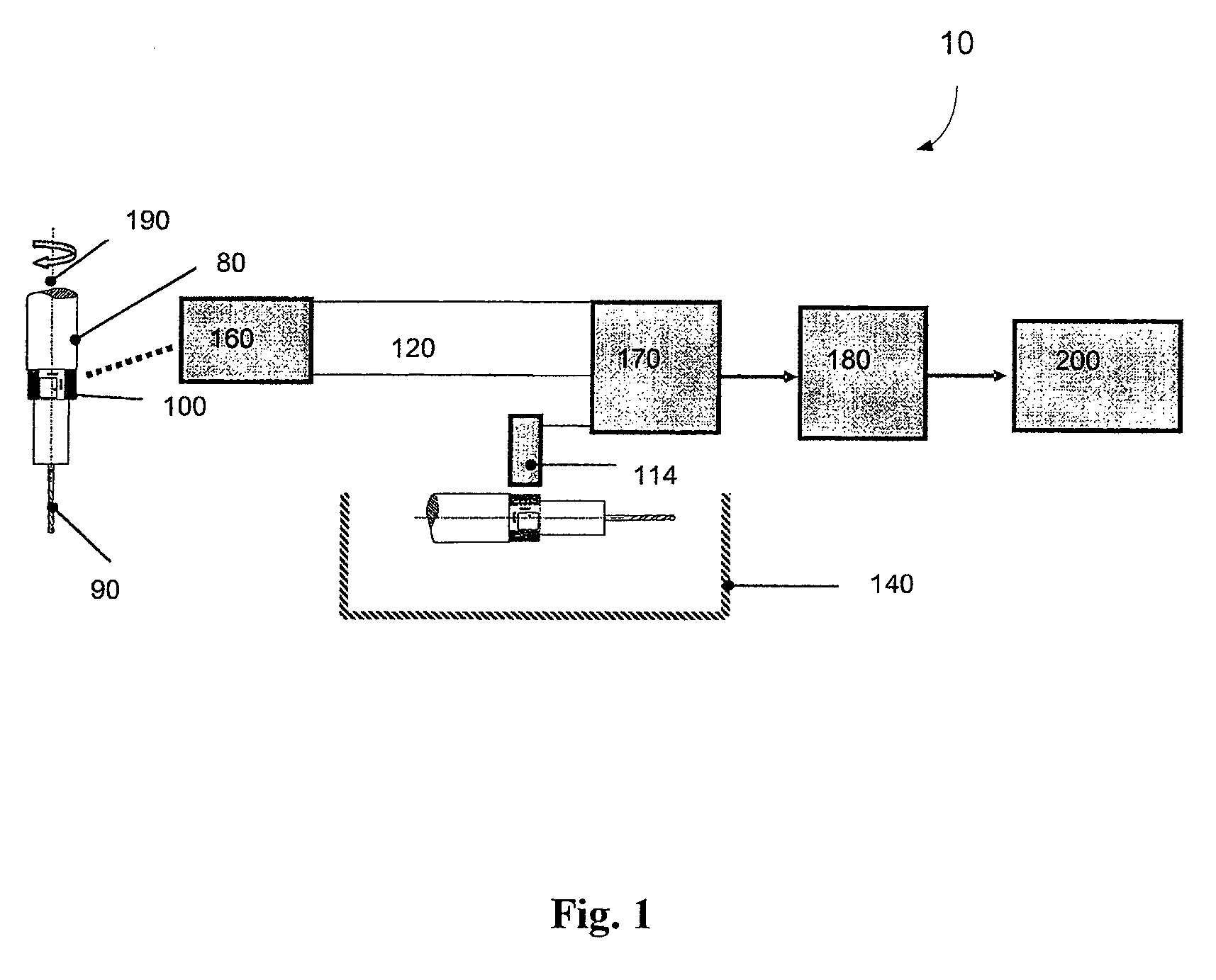
[0022]A comprehensive view of an embodiment of the invention is shown in FIG. 1. Here, sensor 100 is designed as a measuring chuck which is mounted on the tool spindle in a modular way. The precise construction of sensor 100 will be described further below.

[0023]On the left-hand side of FIG. 1, the tool spindle of the machine tool (not shown) with tool holder 80 is displayed in a schematic way. Sensor 100 (the measuring chuck) and tool 90 are fastened to the tool holder 80, wherein all devices can jointly rotate around rotation axis 190 of the tool spindle.

[0024]In this embodiment, the sensor system is designe...


PUM


Abstract

A sensor system for a machine tool with at least one sensor with at least one measurement instrument, which measures a physical quantity occurring within the machine tool, which is related to a machining process performed by the machine tool; with a first energy supply for supply of the at least one measurement instrument of the sensor, wherein the first energy supply receives electric energy from a surrounding electromagnetic field in a wireless way; and with a second energy supply for supplying the at least one measurement instrument of the sensor, wherein the second energy supply comprises at least one battery.

Description

1. TECHNICAL FIELD[0001]The present invention relates to a sensor system for monitoring machining processes in machine tools2. RELATED ART[0002]Modern machine tools perform more and more complex machining processes which are controlled by a program. At the same time a machine tool should be increasingly capable to monitor itself and to take appropriate measures in case of an error. For this purpose, the machine tool needs a sensor system which records the relevant physical quantities during the machining process and which can optionally send the data to a controlling unit of the machine tool.[0003]It is important for such sensor systems that the measurement instruments of the sensor system are mounted near the machining tool or the site of action, in order to record the relevant physical quantities of the machining process. In the case of cutting machine tools the measuring instruments should be mounted e.g. on the tool spindle, in order to be able to measure torques by strain gauge...

Claims


Application Information

Patent Timeline
Patent Type & Authority Patents(United States)
IPC IPC(8): G08B21/00G06F19/00
CPCH02J17/00B23Q1/0009H02J50/10H02J50/90
Inventor LANGE, DIRKREDECKER, VOLKER
Owner ARTIS GES FUR ANGEWANDTE MESSTECHN
Why Eureka
Try Eureka