
Protective layer, composite for forming the protective layer, method of forming the protective layer, and plasma display panel including the protective layer

a technology of protective layer and composite layer, which is applied in the manufacture of electric discharge tubes/lamps, natural mineral layered products, electrode systems, etc., can solve the problems of inability to use as structural materials, difficulty in controlling discharge current, and damage to the dielectric layer by sputtering, etc., to achieve enhanced sputtering resistance, reduce temperature dependency of discharge delay time, and reduce the effect of discharge delay time dependency

Inactive Publication Date: 2010-05-11
SAMSUNG SDI CO LTD
View PDF15 Cites 3 Cited by
  • Summary
  • Abstract
  • Description
  • Claims
  • Application Information

AI Technical Summary

Benefits of technology

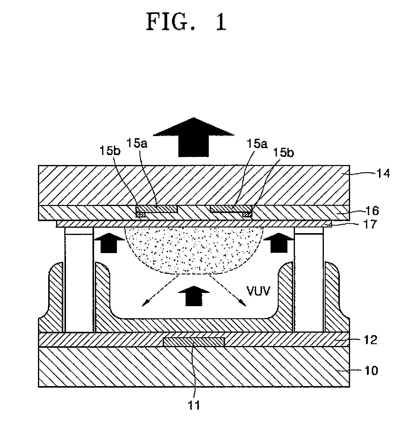
The MgO-based protective layer with rare earth elements reduces discharge delay time and its temperature dependency, improving the panels' discharge characteristics, enabling faster addressing, increased brightness, and enhanced reliability, while also providing improved sputtering resistance.

Problems solved by technology

However, when only an electrode is used, it may be difficult to control a discharge current.
On the other hand, when only an electrode and a dielectric layer are used, damage to the dielectric layer by sputtering may occur.
The MgO composite ceramics have been developed considering that MgO has good heat resistance, corrosion resistance, and insulating property but cannot be used as a structural material since it has poor strength, fracture toughness, and thermal shock resistance.
However, since protective layers for PDPs may significantly affect the discharge characteristics of the PDPs, in particular, a discharge delay time and the temperature dependency of the discharge delay time, developments of new protective layers considering the discharge characteristics are needed.

Method used


Image

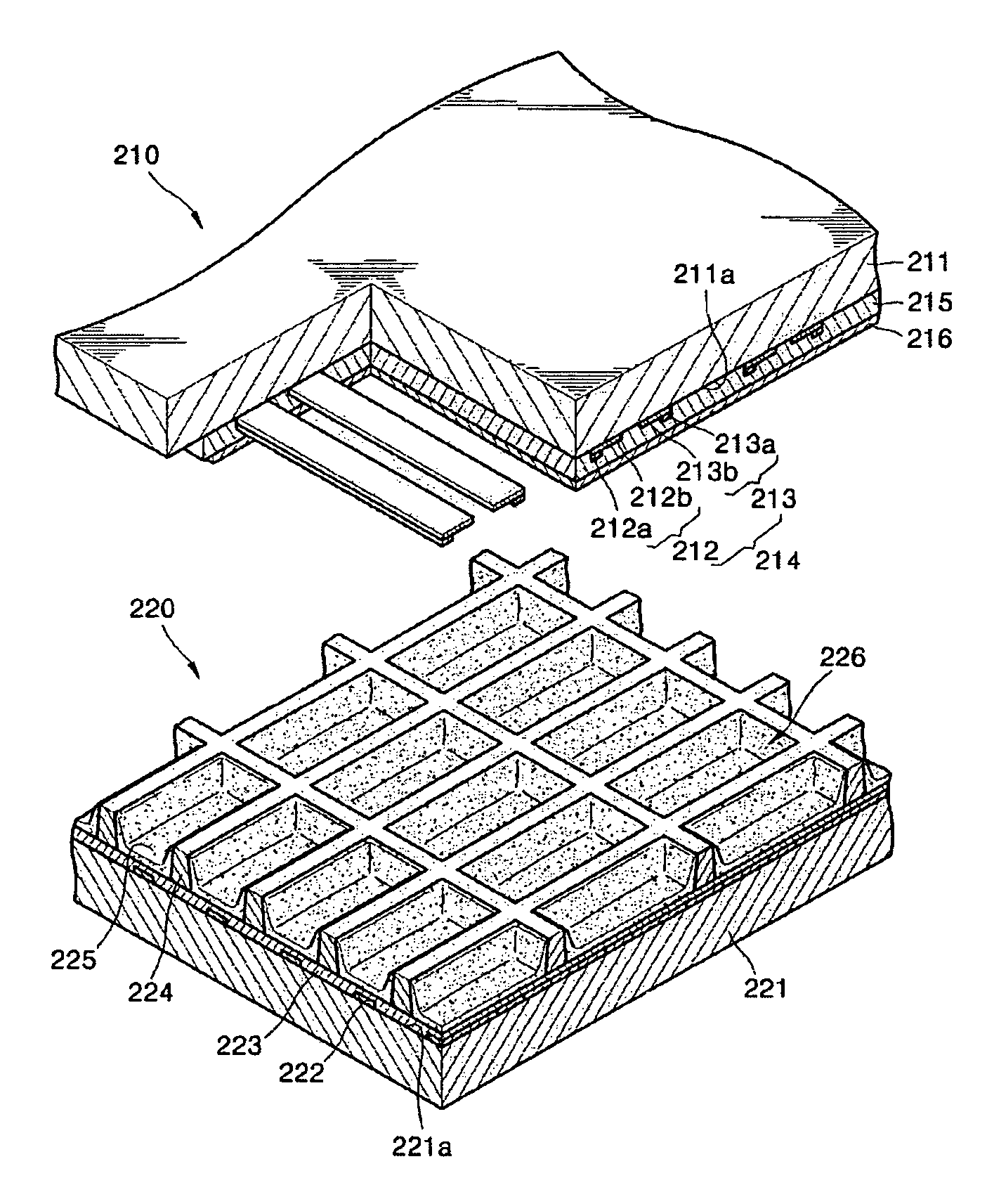
  • Protective layer, composite for forming the protective layer, method of forming the protective layer, and plasma display panel including the protective layer
  • Protective layer, composite for forming the protective layer, method of forming the protective layer, and plasma display panel including the protective layer
  • Protective layer, composite for forming the protective layer, method of forming the protective layer, and plasma display panel including the protective layer

Examples


manufacturing example 1

Manufacturing of Discharge Cell

[0096]MgO and Sc2O3 were mixed so that the content of scandium was 5.0×10⁻⁵ g per 1 g of MgO, and stirred in a mixer for 5 hours or more, to obtain a uniform mixture. MgF2 used as a flux was added to the mixture, stirred, placed in a crucible, and heated at 900° C. for 5 hours. The resultant product was compression-molded into pellets and heated at 1,650° C. for 3 hours, to prepare a composite for forming a protective layer containing 5.0×10⁻⁵ g of scandium per 1 g of MgO.

[0097]Meanwhile, a glass (PD 200 Glass) of 22.5×35×3 mm in size was prepared. An Ag electrode was formed in a predetermined pattern on an upper surface of the glass. Then, the Ag electrode was covered with a PbO glass to form a PbO dielectric layer with a thickness of about 30 to 40 μm. The composite for forming the protective layer was deposited on an upper surface of the dielectric layer to form a protective layer with a thickness of 700 nm. The above processes were further repeated...

manufacturing example 2

[0104]A discharge cell (Sample 2) was manufactured in the same manner as in Manufacturing Example 1 except that a composite for forming a protective layer was prepared by mixing MgO and Sc2O3 so that the Sc content was 1.5×10⁻⁴ g per 1 g of MgO, and protective layers in which the Sc content was 1.5×10⁻⁴ g (150 ppm) per 1 g of MgO were formed using the composite for forming the protective layer.

manufacturing example 3

[0105]A discharge cell (Sample 3) was manufactured in the same manner as in Manufacturing Example 1 except that a composite for forming a protective layer was prepared by mixing MgO and Sc2O3 so that the Sc content was 3.0×10⁻⁴ g per 1 g of MgO, and protective layers in which the Sc content was 3.0×10⁻⁴ g (300 ppm) per 1 g of MgO were formed using the composite for forming the protective layer.


PUM

PropertyMeasurementUnit
angleaaaaaaaaaa
sizeaaaaaaaaaa
sizeaaaaaaaaaa

Abstract

Provided are a protective layer made of magnesium oxide containing at least one rare earth element selected from the group consisting of the rare earth elements, in which the content of the at least one rare earth element is from about 5.0×10⁻⁵ to about 6.0×10⁻⁴ per 1 part by weight of the magnesium oxide, a composite for forming the protective layer, a method of forming the protective layer, and a plasma display panel including the protective layer. The protective layer can reduce a discharge delay time and the temperature dependency of the discharge delay time, and thus, is suitable for single scan and an increase in Xe content.

Description

CROSS-REFERENCE TO RELATED APPLICATION[0001]This application claims the priority of Korean Patent Application No. 10-2004-0108075, filed on Dec. 17, 2004, and No. 10-2005-0002436, filed on Jan. 11, 2005, in the Korean Intellectual Property Office, the disclosures of which are incorporated herein in their entireties by reference.BACKGROUND OF THE INVENTION[0002]1. Field of the Invention[0003]The present embodiments relate to a protective layer, a composite for forming the protective layer, a method of forming the protective layer, and a plasma display panel including the protective layer. More particularly, the present embodiments relate to a protective layer made of magnesium oxide containing a predetermined amount of a rare earth element which has a short discharge delay time with little temperature dependency, a composite for forming the protective layer, a method of forming the protective layer, and a plasma display panel including the protective layer.[0004]2. Description of the...

Claims


Application Information

Patent Timeline
Patent Type & Authority Patents(United States)
IPC IPC(8): B32B9/00C04B35/04C23C14/08C23C14/24C23C14/34H01J9/02H01J11/12H01J11/22H01J11/24H01J11/26H01J11/34H01J11/40
CPCC03C17/36C03C17/3642C03C17/3657H01J11/40H01J11/12C03C17/3671C03C2217/40
Inventor LEE, MIN-SUKCHOI, JONG-SEOKIM, SUK-KIMATULEVICH, YURIKIM, JAE-HYUKSUH, SOON-SUNG
Owner SAMSUNG SDI CO LTD
Learn More