
Image sensor using back-illuminated photodiode and method of manufacturing the same

a photodiode and image sensor technology, applied in the field of image sensors, can solve the problems of color crosstalk, deterioration, heat treatment cannot be performed at a high temperature, and light sensitivity, so as to reduce noise and crosstalk and improve sensitivity.

Active Publication Date: 2010-05-11
SK HYNIX INC
View PDF9 Cites 35 Cited by
  • Summary
  • Abstract
  • Description
  • Claims
  • Application Information

AI Technical Summary

Benefits of technology

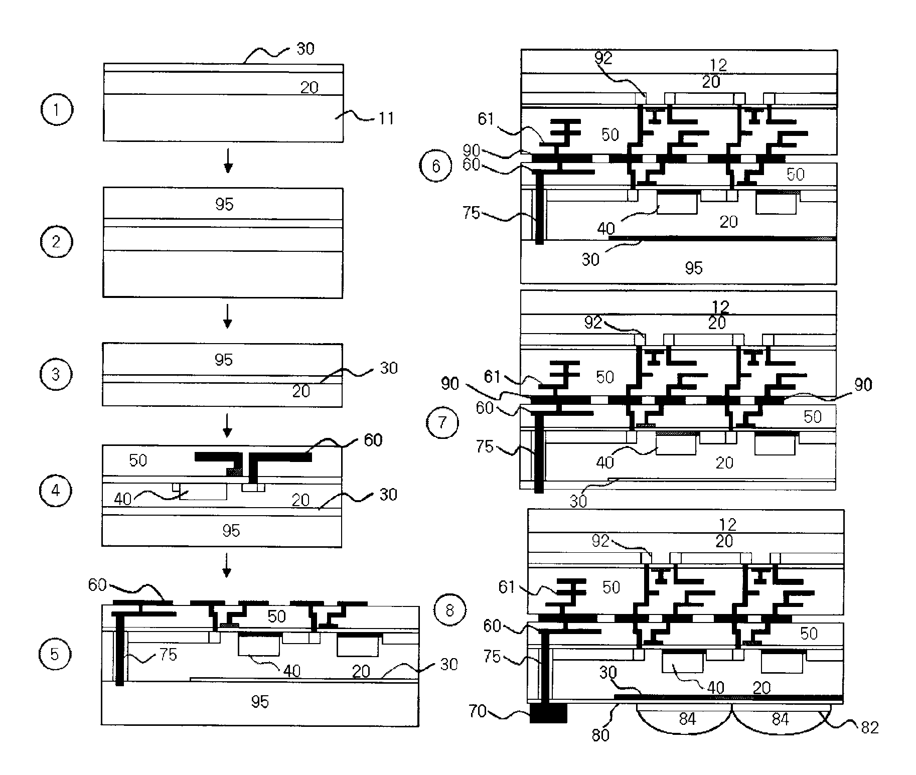
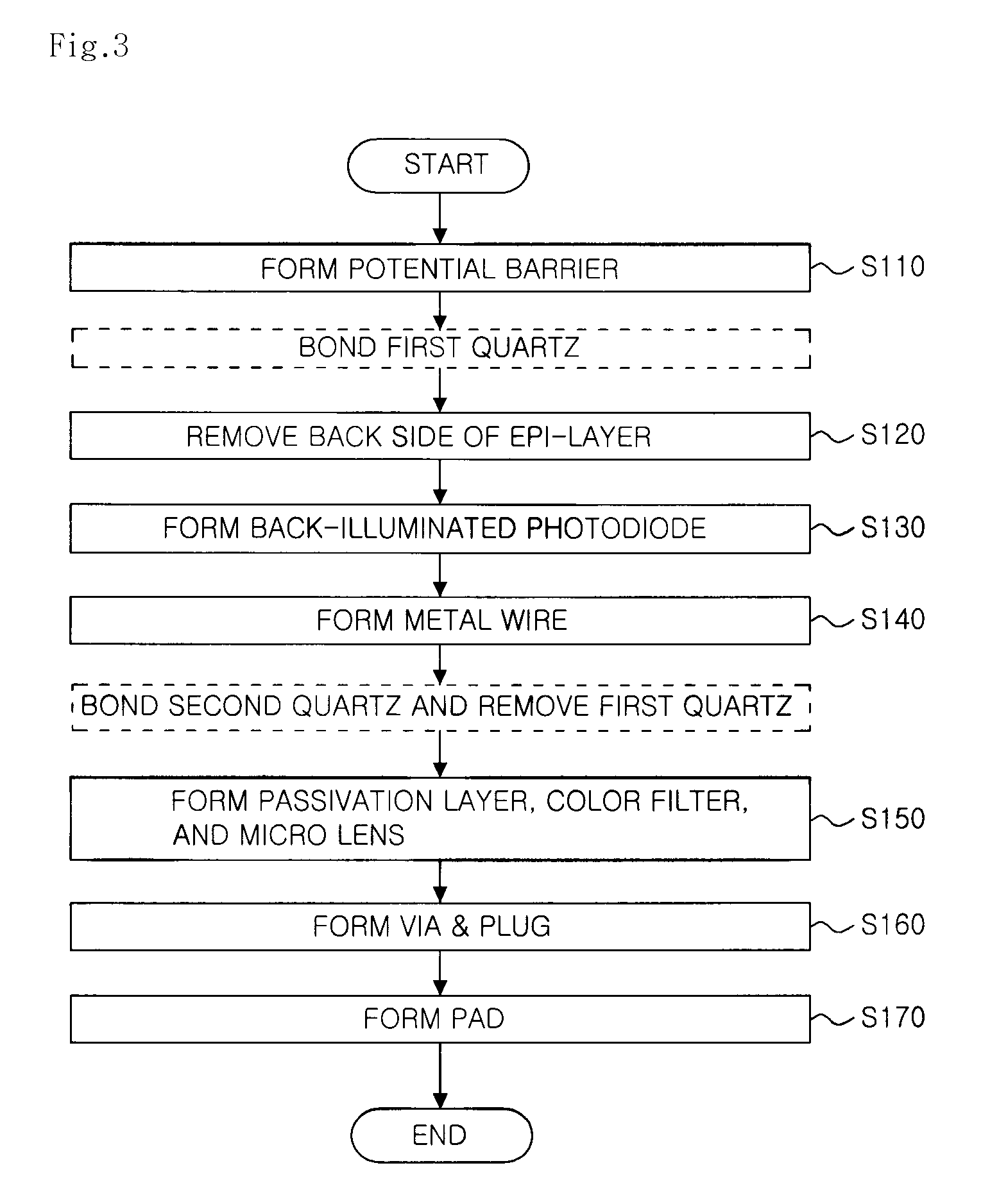
The present invention provides an image sensor using a back-illuminated photodiode that absorbs light through its bottom side, reducing noise and crosstalk. The sensor includes an epi-layer formed on a specific type of wafer, a potential barrier formed on the epi-layer, a back-illuminated photodiode formed on the epi-layer, a logic circuit formed on a specific region of the wafer, a metal bonding portion by which a metal wire connected to the back-illuminated photodiode is electrically connected to a metal wire connected to the logic circuit, a pad formed on the potential barrier, and a via formed through the epi-layer and a plug that fills the via so that the pad is electrically connected to the logic circuit. The method of manufacturing the image sensor includes the steps of forming epi-layers with low concentration on wafers, forming a potential barrier on one of the epi-layers, removing the back side of the wafer, forming a back-illuminated photodiode and logic circuit on the exposed epi-layer, adding an inter-metal dielectric layer and metal wire to connect the photodiode and logic circuit, adding a via and plug to connect the logic circuit, and adding a passivation layer, color filter, and micro-lens. The technical effects of the invention include improved sensitivity, reduced noise, and improved crosstalk reduction.

Problems solved by technology

Throughout this process, sensitivity of light, particularly, blue light, deteriorates.
This affects an adjacent photodiode, resulting in a color crosstalk.
However, there has been a problem in that heat treatment cannot be performed at a high-temperature because of the existing metal wire.
Therefore, the conventional image sensor using the back-illuminated photodiode cannot solve a noise problem that is resulted from a defected surface of a silicon substrate on which the back-illuminated photodiode is formed.

Method used


Image

  • Image sensor using back-illuminated photodiode and method of manufacturing the same
  • Image sensor using back-illuminated photodiode and method of manufacturing the same
  • Image sensor using back-illuminated photodiode and method of manufacturing the same

Examples


Embodiment Construction

[0022]Hereinafter, exemplary embodiments of the present invention will be described in detail with reference to the accompanying drawings.

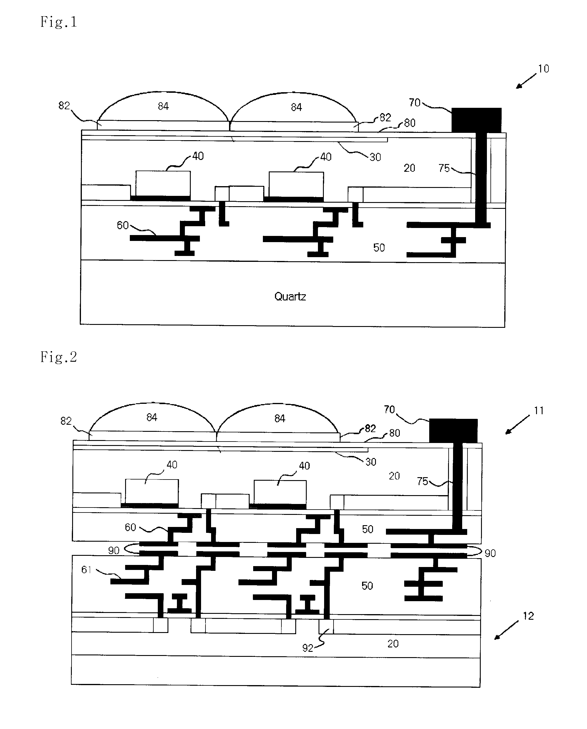
[0023]FIG. 1 is a cross-sectional view of a structure of an image sensor using a back-illuminated photodiode according to an embodiment of the present invention. The image sensor is formed of a specific type of wafer 10, an epitaxial layer (or epi-layer) 20, a potential barrier 30, a back-illuminated photodiode 40, an inter-metal dielectric (IMD) layer 50, a metal wire 60, a pad 70, a via & plug 75, a passivation layer 80, a color filter 82, and a micro-lens 84.

[0024]The potential barrier 30 is formed on a surface of the epi-layer 20 with low concentration by doping impurities having the same type as the epi-layer 20 and having higher concentration than the epi-layer 20.

[0025]The potential barrier 30 may be formed by using ion implantation, epitaxial growth, or boro silicate glass (BSG) deposition.

[0026]The back-illuminated photodiode 40 is formed...


PUM


Abstract

An image sensor using a back-illuminated photodiode and a manufacturing method thereof are provided. According to the present invention, since a surface of the back-illuminated photodiode can be stably treated, the back-illuminated photodiode can be formed to have a low dark current, a constant sensitivity of blue light for all photodiodes, and high sensitivity. In addition, it is possible to manufacture an image sensor with high density by employing a three dimensional structure in which a photodiode and a logic circuit are separately formed on different substrates.

Description

BACKGROUND OF THE INVENTION[0001]1. Field of the Invention[0002]The present invention relates to an image sensor, and more particularly, to an image sensor using a back-illuminated photodiode which absorbs light through its bottom side and a method of manufacturing the image sensor.[0003]2. Description of the Related Art[0004]A complementary metal-oxide semiconductor (CMOS) image sensor is a device for measuring light intensity. In general, such image sensor has a structure in which a photodiode is formed on a plane where a digital / analog circuit is formed, and a metal wire and an inter-metal dielectric (IMD) layer are formed on a top side of the photodiode.[0005]In the conventional image sensor, light passes through a micro-lens and a color filter and thereafter proceeds along a pathway of several films before being absorbed by the photodiode. Throughout this process, sensitivity of light, particularly, blue light, deteriorates.[0006]Furthermore, in the conventional image sensor, a...

Claims


Application Information

Patent Timeline
Patent Type & Authority Patents(United States)
IPC IPC(8): H01L31/0232H01L31/102H04N25/00
CPCH01L27/14687H01L27/14636H01L27/1464H01L27/14632H01L27/14621H01L27/14627H01L27/146
Inventor LEE, BYOUNG SUWON, JUN HO
Owner SK HYNIX INC
Learn More