Hybrid laser and resistance welding system and method

a laser and resistance welding technology, applied in the field of welding systems, can solve the problems of poor gap bridgeability, relative high cost of high-powered lasers, and limited systems, and achieve the effect of increasing the efficiency of laser welding

Inactive Publication Date: 2010-05-18
GM GLOBAL TECH OPERATIONS LLC +1
View PDF13 Cites 9 Cited by
  • Summary
  • Abstract
  • Description
  • Claims
  • Application Information

AI Technical Summary

Benefits of technology

[0009]Responsive to these and other concerns caused by conventional laser welding systems, the present invention provides an improved system for decreasing the costs and structural inefficiencies associated therewith. This invention provides a method of welding workpieces using multiple sources for in tandem pre-heating and welding. The invention is further useful, among other things, for substantially pre-heating the workpieces with a heating unit, to increase the applicability of low-powered laser welding.
[0011]A second aspect of the present invention concerns a method of increasing the efficiency of laser-welding a plurality of workpieces. The method preferably comprises the steps of pre-heating a portion of the workpieces to a minimum temperature using a heating unit, further heating the portion with a laser beam until the first portion melts, and cooling the portion to a temperature less than the melting range, so as to allow the portion to re-solidify and form a weld.

Problems solved by technology

However, while these benefits help minimize stresses experienced by the workpieces, they present other concerns.
For example, these systems are typically limited by strict requirements of tolerance, porosity formation, poor gap bridgeability and hot cracking in the weld.
Of further concern are the relative high costs associated with high-powered lasers (i.e., lasers having a power output greater than 4 kW), which are not solely a result of increased input energy demands.
These systems may also present construction concerns, where a high-powered laser is utilized to produce the fusion weld.
The formation of pores and cracking further reduces the structural integrity of the weld.
As with conventional laser welding, these hybrid systems often require high powered laser output for, and therefore, experience the same concerns during combination welding.

Method used


Image

  • Hybrid laser and resistance welding system and method
  • Hybrid laser and resistance welding system and method
  • Hybrid laser and resistance welding system and method

Examples


Embodiment Construction

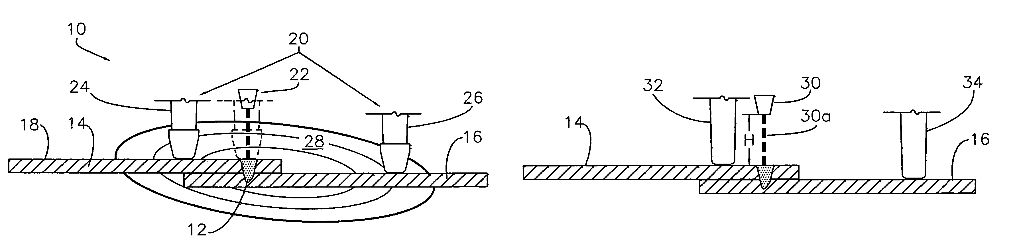
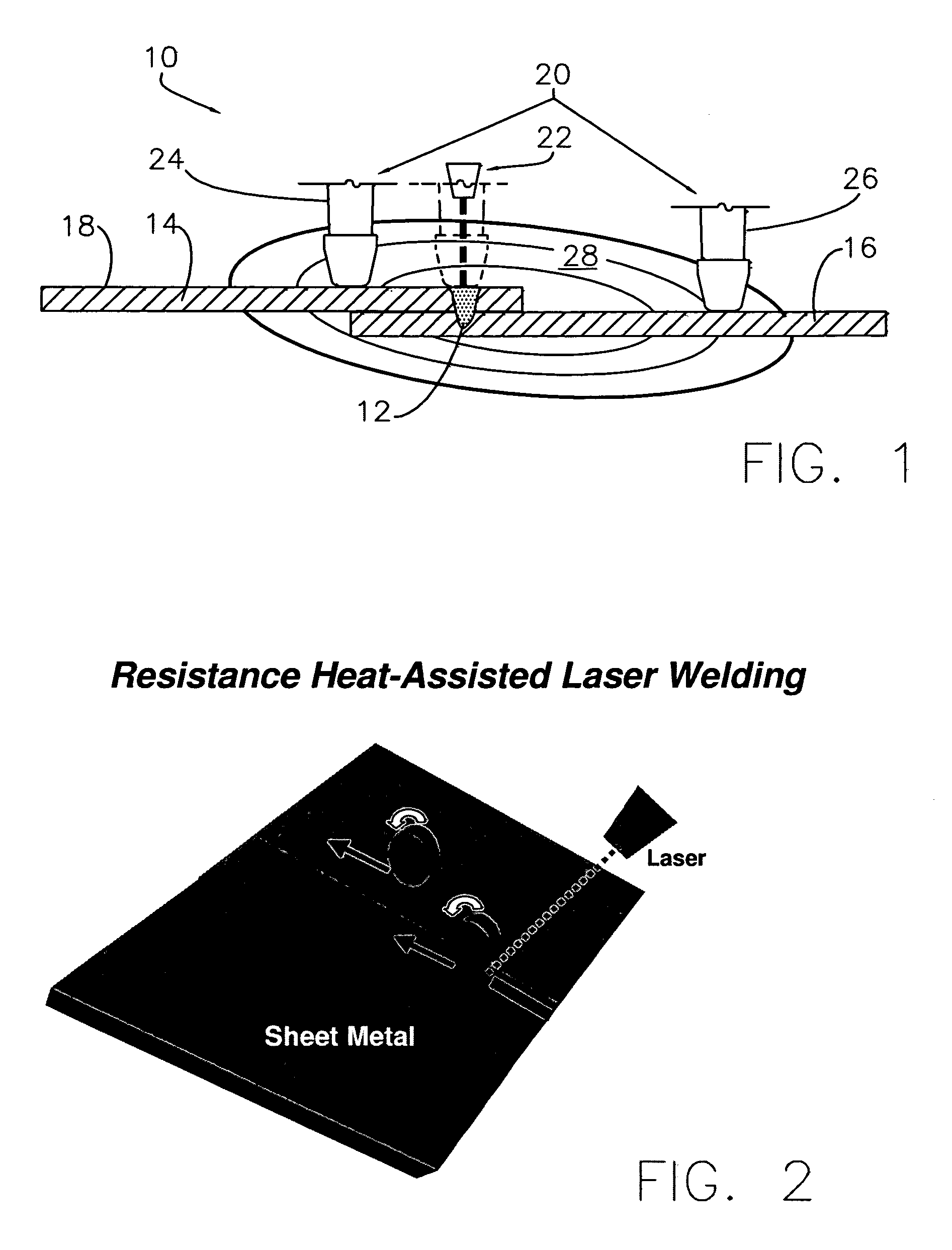
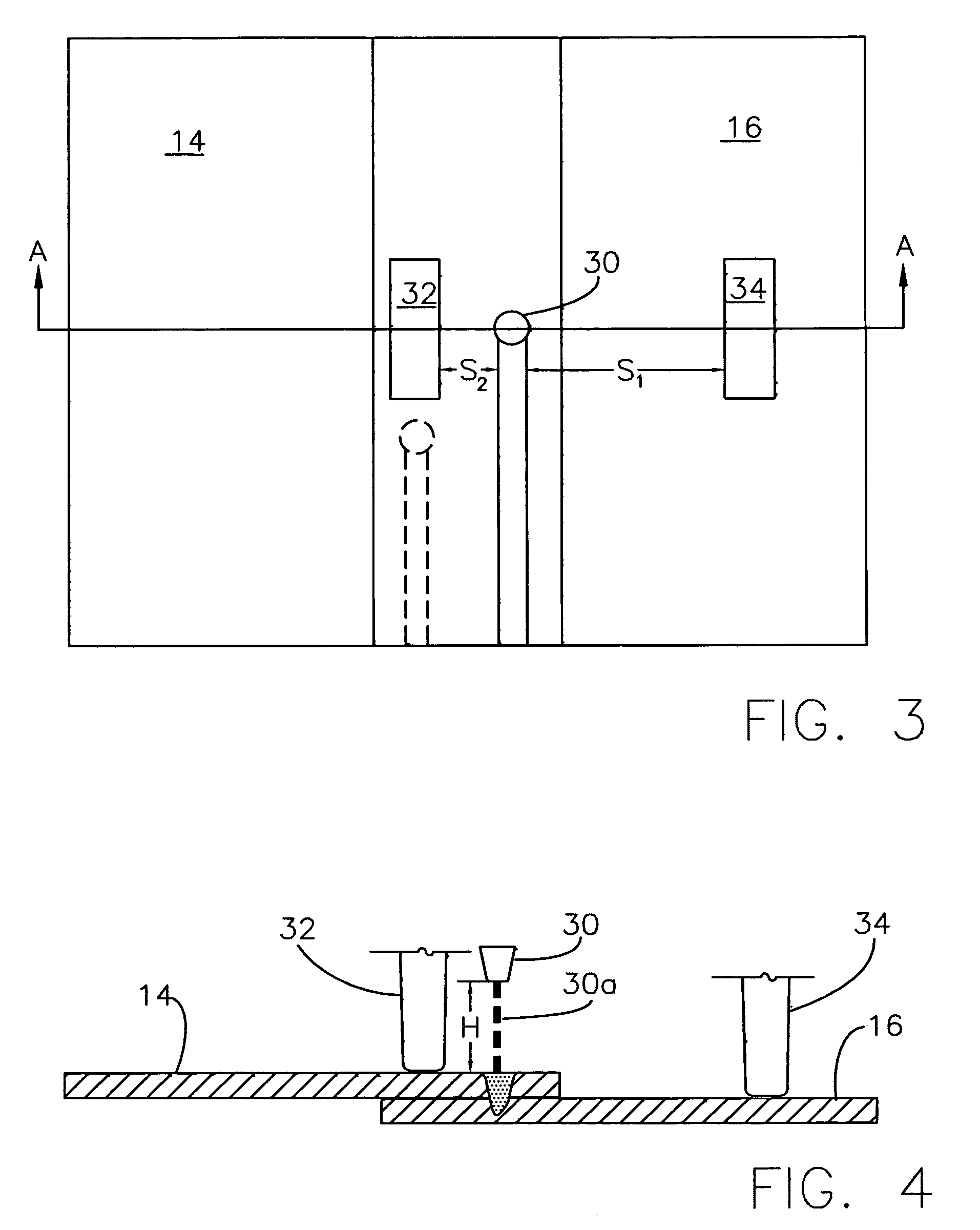
[0018]The present invention concerns an improved fusion welding system 10 for welding a plurality (i.e., two or more) of overlapping adjacent workpieces, such as automotive sheet metal and engine cradle parts, to produce a weld 12. In the illustrated embodiments shown in FIGS. 1 through 4, a plurality of two workpieces 14,16 of equal thickness are shown; however, the system 10 may be utilized to weld a greater plurality or structural components having variable thickness. The workpieces may be formed of a wide range of materials including iron alloys, aluminum alloys, magnesium alloys, titanium and molybdenum. As shown in FIG. 1, the positioned workpieces 14,16 present at least one outermost surface 18 that defines in part an outer edge and is exposed to the system 10. To facilitate accessibility, the system 10 preferably presents a single-sided process, in that it engages the workpieces 14,16 along surface 18 only. In this configuration, the workpieces 14,16 are supported on the opp...


PUM

PropertyMeasurementUnit
poweraaaaaaaaaa
thicknessaaaaaaaaaa
thicknessesaaaaaaaaaa

Abstract

An improved fusion welding system having a heating unit and welding device is adapted for increasing the efficiency of welding a plurality of workpieces. The system preferably presents a single-sided process, and includes first and second electrode wheels operable to heat a portion of the workpieces to a minimum temperature, and a translatable laser cooperatively configured to form a continuous weld within the heated portion. The preferred system provides the advantages of laser welding, such as precision, while enabling weld production at lower laser power outputs or faster welding speeds than conventional laser welding systems.

Description

BACKGROUND OF THE INVENTION[0001]1. Field of the Invention[0002]The present invention relates to welding systems, and more particularly to a fusion welding system including a heating unit and welding device for combination heating and welding.[0003]2. Discussion of Prior Art[0004]The process of material joining and treatment is a necessary condition for the industrial progress. As such, fusion-welding systems have been developed for joining multi-component workpieces. One such system, laser spot and seam welding utilizes laser heat energy during joining, and is commonly used, for example, in the automotive industry.[0005]These conventional systems are typically used to provide faster welding speeds and produce more accurate and precise welds than do counterpart resistance welding technologies. The power associated with the laser, and the material composition and initial state of the workpieces are directly proportional to the aspect ratio of weld depth to width. In other words, the ...

Claims


Application Information

Patent Timeline
Patent Type & Authority Patents(United States)
IPC IPC(8): B23K11/06B23K11/10B23K26/00
CPCB23K11/061B23K11/11B23K28/02B23K26/246B23K2201/18B23K26/244B23K2101/18
Inventor WANG, PEI-CHUNGZHAO, XIHUAZHAO, HE
Owner GM GLOBAL TECH OPERATIONS LLC
Why Eureka
Try Eureka