Eureka AIR delivers breakthrough ideas for toughest innovation challenges, trusted by R&D personnel around the world.

Dual-modulus prescaler circuit operating at a very high frequency

a prescaler circuit and dual-modulus technology, applied in the direction of pulse technique, oscillation generator, counting chain synchronous pulse counter, etc., can solve the problems of prescaler circuits that are not provided to operate normally at a very high frequency, prescaler circuits consume a significant amount of electrical power, etc., and achieve the effect of reducing the electrical power consumption of said circuits

Active Publication Date: 2010-05-18
THE SWATCH GRP RES & DEVELONMENT LTD
View PDF10 Cites 11 Cited by
  • Summary
  • Abstract
  • Description
  • Claims
  • Application Information

AI Technical Summary

Benefits of technology

[0011]It is thus an object of the invention to provide a dual-modulus prescaler circuit, which overcomes the aforementioned drawbacks of the state of the art, with a relatively simple structure, made in CMOS technology and which operates at a very high frequency.
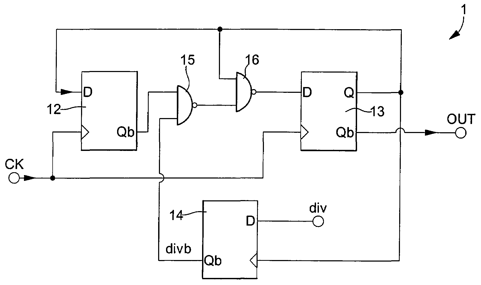
[0014]One advantage of the prescaler circuit according to the invention is that it includes two NAND logic gates, which are made with two NMOS transistors in series, which are connected in series to two parallel PMOS transistors between two terminals of a continuous voltage source. Since each NMOS transistor switches rapidly compared to each PMOS transistor, each NAND logic gate forms a prescaler circuit capable of operating at a very high frequency.
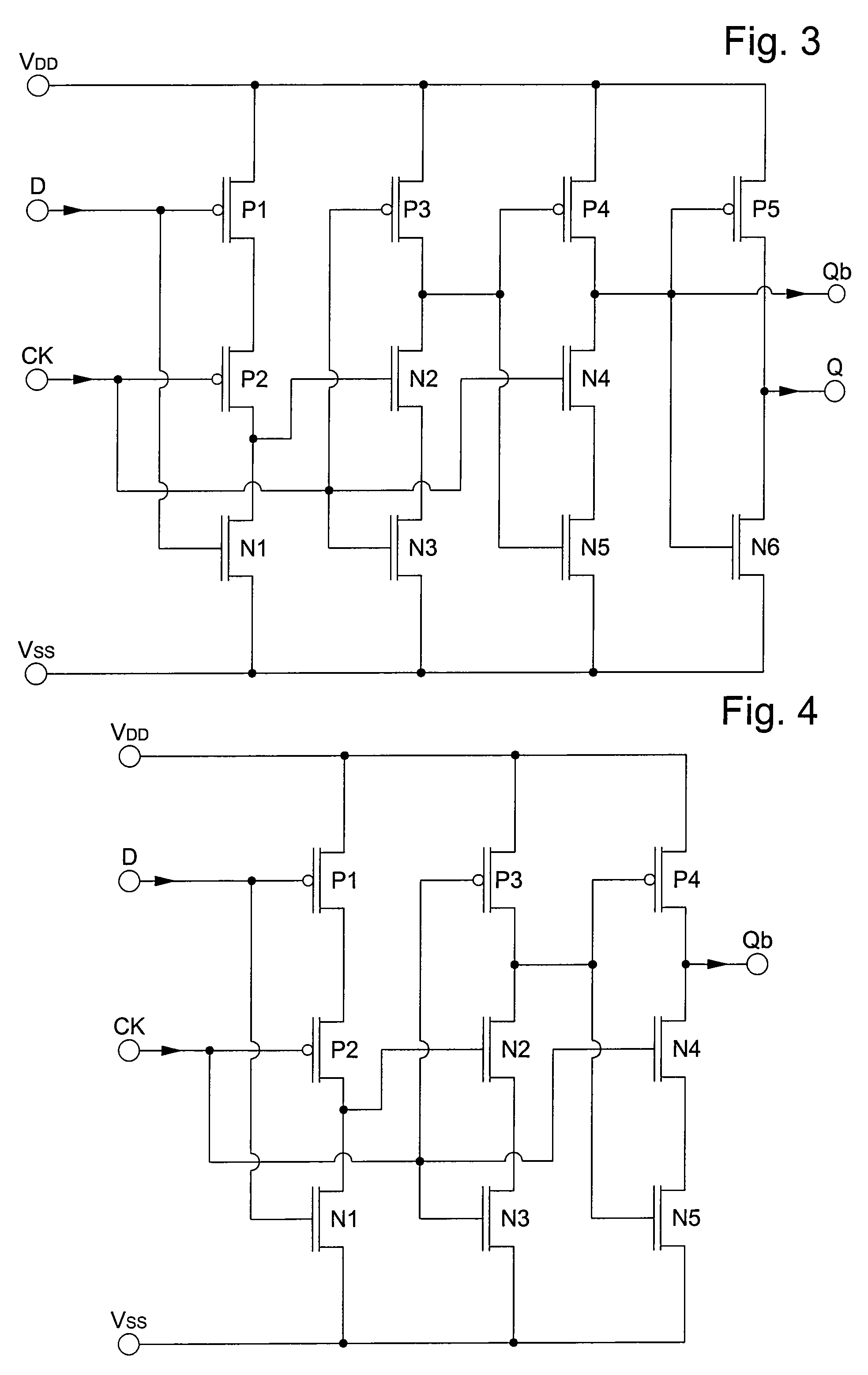
[0015]One of the two flip flops advantageously provides only one output signal through an inverted output, which means that this flip flop can be made with one active branch less than a standard D-type flip flop in order to reduce the electrical power consumption of said circuit. The D-type flip flops are advantageously dynamic flip flops for the dual-modulus prescaler circuit, capable of operating at a very high frequency.

Problems solved by technology

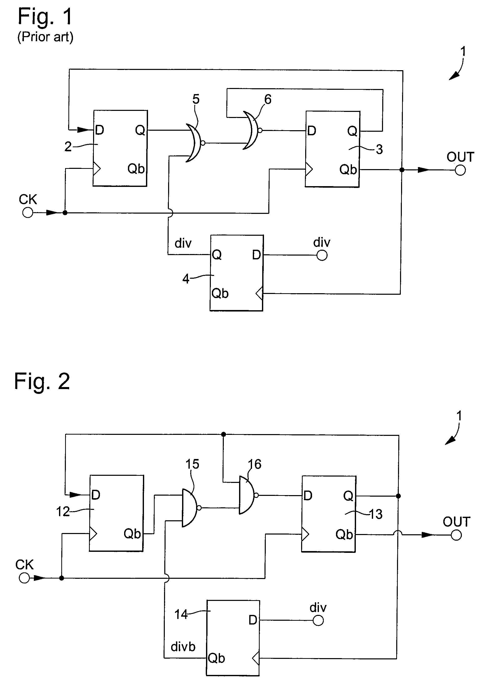
Due to the use of NOR logic gates with two PMOS transistors in series that are slow, this type of prescaler circuit is not provided to operate normally at a very high frequency, which constitutes a drawback.
Moreover, since three standard D-type flip flops are used, this prescaler circuit consumes a significant amount of electrical power.

Method used


Image

  • Dual-modulus prescaler circuit operating at a very high frequency
  • Dual-modulus prescaler circuit operating at a very high frequency
  • Dual-modulus prescaler circuit operating at a very high frequency

Examples


Embodiment Construction

[0021]In the following description, the dual-modulus prescaler or counter-divider circuit is devised to be able to operate normally at a very high frequency, particularly in the phase lock loop of a frequency synthesiser. Of course, it may also include, in addition to the divider-by-2 or divider-by-3 assembly, a chain of dividers preferably connected to the output of the assembly. The circuit can thus divide the frequency of a very high frequency signal by a first factor N, where N is at least an integer number higher than or equal to 2, or by a second factor N+M, where M is at least an integer number higher than or equal to 1.

[0022]FIG. 2 shows a simplified structure of a dual-modulus prescaler circuit 1 according to the invention, capable of operating at a very high frequency, for example for dividing a frequency of the order of 2.45 GHz. This prescaler or counter-divider circuit includes at least one assembly, which is made up of two dynamic D-type flip flops 12 and 13, and two N...


PUM


Abstract

The dual-modulus prescaler circuit (1) is devised to operate at a very high frequency. This circuit includes an assembly formed of two dynamic D-type flip flops (12, 13), and two NAND logic gates (15, 16) arranged in negative feedback between the two flip flops. The two flip flops are clocked by an input clock signal (CK) to supply a divided output signal (OUT) whose frequency matches the input clock frequency divided by 2 or by 3 as a function of a division mode selection signal (divb) applied to the input of the first NAND logic gate (15). One non-inverted output of the second flip flop is connected to one input of the first flip flop (12). The first dynamic flip flop includes three active branches and supplies a single inverted output signal. A third flip flop (14) with three active branches receives an inverted mode selection signal (div) at input in order to supply the mode selection signal to the inverted output thereof, clocked by the non-inverted output signal of the second flip flop.

Description

[0001]This application claims priority from European Patent Application No. 07122935.5 filed Dec. 11, 2007, the entire disclosure of which is incorporated herein by reference.FIELD OF THE INVENTION[0002]The invention concerns a dual-modulus prescaler circuit operating at a very high frequency in particular arranged in a phase lock loop of a frequency synthesiser. The counter-divider or prescaler circuit includes at least an assembly comprising two dynamic D-type flip flops, and two logic gates arranged in negative feedback between the two flip flops. These two flip flops are clocked by an input clock signal to supply an output signal whose frequency matches the input clock signal divided by a first factor equal to 2, or by a second factor equal to 3 in accordance with the selected division mode.[0003]It should be noted that “very high frequency signals” are signals with a higher frequency than 1 GHz. This very high frequency is, for example, the carrier frequency of a transmission c...

Claims


Application Information

Patent Timeline
Patent Type & Authority Patents(United States)
IPC IPC(8): H03K21/00H03K23/00
CPCH03K23/667H03K23/44H03K23/64H03L7/183
Inventor CASAGRANDE, ARNAUDVELASQUEZ, CARLOSAREND, JEAN-LUC
Owner THE SWATCH GRP RES & DEVELONMENT LTD
Why Eureka
Eureka Blog
Learn More