Determination of the connected heating load of a building

Inactive Publication Date: 2010-05-18
DONATH MARTIN +1
View PDF18 Cites 16 Cited by
  • Summary
  • Abstract
  • Description
  • Claims
  • Application Information

AI Technical Summary

Benefits of technology

[0013]According to the present invention, an advantage of the system described herein is that the actual degree of utilization is included in the calculations of the heat performance transferred from the heating system to the building, in particular as a function of the operating behavior. The present invention is based on the understanding that the efficiency may fluctuate greatly over time. According to the present invent

Problems solved by technology

As a result, the efficiency specified by heating boiler manufacturers deviates substantially in many cases from the degree of utilization achieved during operation in practice.
This is due, among other things, to the fact that systems of this type were frequently overdimensioned due to a false understanding of “the need for safety and comfort.” This applies not only to private systems, but to a large extent also to buildings used for public and commercial purposes.
The consequence of this overdimensioning is that the thermal systems are operated in uneconomical partial load situations for most of the heating period.
This unsatisfactory situation results in the need to determine the actual heat requirements of a building to be heated to improve the building's energy efficiency so that the heating system can be optimally adapted thereto.
This method is controversial due to the somewhat subjective evaluation factors, resulting in the need for a method base

Method used


Image

  • Determination of the connected heating load of a building
  • Determination of the connected heating load of a building
  • Determination of the connected heating load of a building

Examples


Embodiment Construction

[0065]Referring now to the figures of the drawing, the figures comprise a part of this specification and illustrate exemplary embodiments of the described system. It is to be understood that in some instances various aspects of the system may be shown schematically or may be exaggerated or altered to facilitate an understanding of the system.

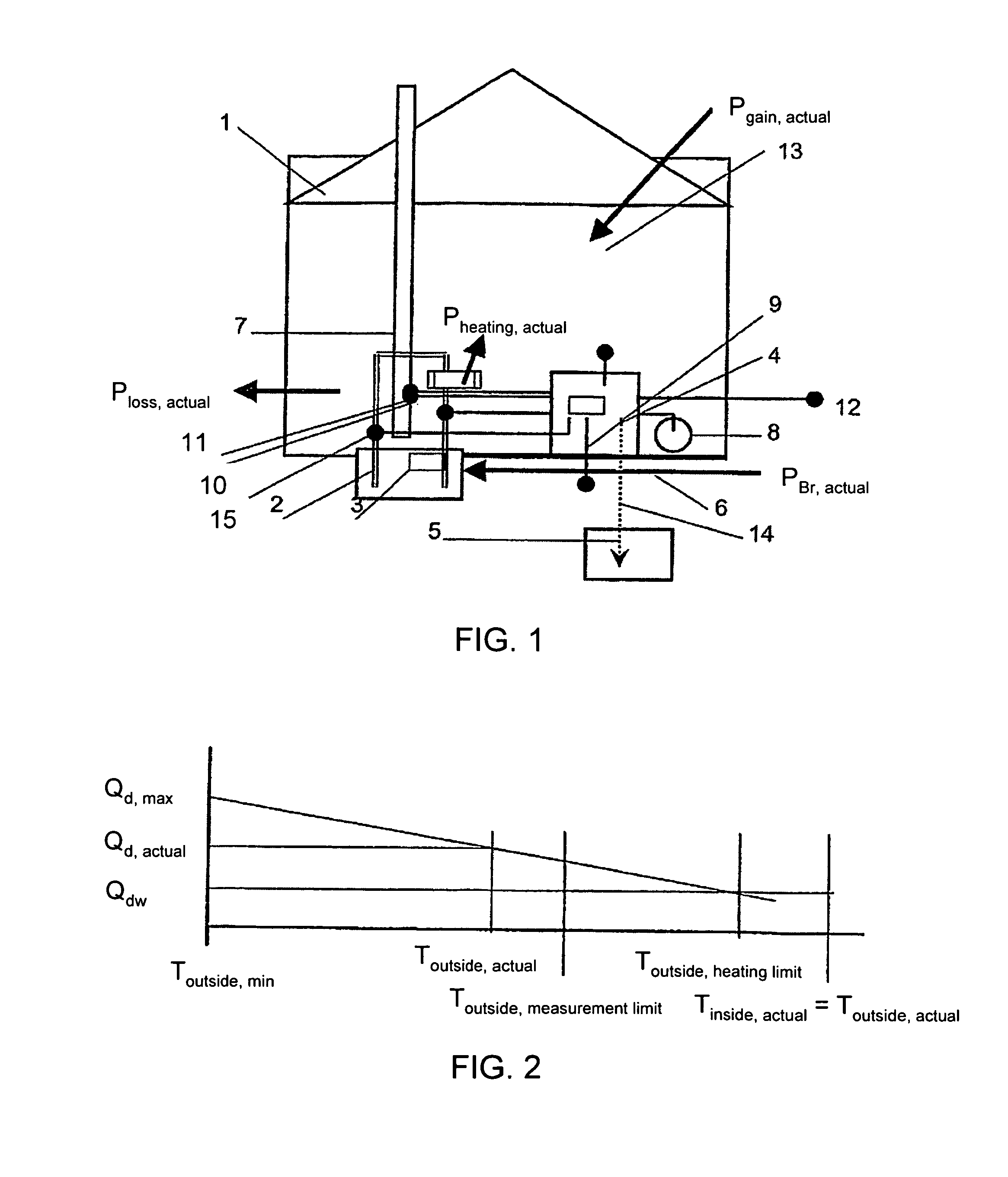
[0066]In the case of the system according to FIG. 1, a heating system 2 including a boiler 3 (having a burner which is not illustrated in greater detail) is accommodated in a building 1 for the purpose of heating building 1, the heating system being fired by fossil fuel 6 such as oil or gas, or by renewable fuels such as pellets. Fuel power PBr, actual contained in fuel 6 is converted to a useful power Pheating, actual, the heating system having an efficiency ηK, so that useful power Pheating, actual generated by the heating system is equal to the product of efficiency ηK and fuel power PBr, actual. In addition, power loss Ploss, actual is withd...


PUM


Abstract

A method and device, wherein the following steps are carried out: measurement or determination of waste gas concentration parameters, waste gas temperature, outside temperature, fuel power during a limited observation period; determination of the efficiency of the heating system in the area of observation over a period of time; determination of the average outside temperature in the area of observation; determination of heating performance produced in accordance with an average outside temperature on the basis of fuel power over a period of time and the efficiency of the heating system over a period of time in the area of observation; determination of maximum heating performance which is to be obtained in accordance with a minimum outside temperature from the average heating performance, minimum outside temperature, average inside temperature and average outside temperature in the area of observation; determination of the heat contact value of the heating system from the maximum heating performance and duration of observation.

Description

TECHNICAL FIELD[0001]The present invention relates to a method and a device for determining the connected heating load (also known as the heating load) of a building heated by a heating system, the heating system being fired by fuel in a waste gas-generating manner and an outside temperature as well as an inside temperature occurring for the building.BACKGROUND OF THE INVENTION[0002]The efficient use of energy is urgently needed from an economical and ecological perspective. Energy conservation is therefore a measure for both lowering costs and protecting the environment, and it can be achieved either by cutting energy use or through intelligent technical solutions. The energy-related and environmental performance of heating boilers has a great deal to do with this issue. Up to now, evaluations of energy efficiency were based mainly on static approaches. However, the interaction between the system and building is dynamic. As a result, the efficiency specified by heating boiler manuf...

Claims


Application Information

Patent Timeline
IPC IPC(8): F23N5/24G05B15/00G05B21/00G06F17/40G06F19/00G01K17/06
CPCG01K17/20G01K17/06
Inventor DONATH, MARTINHOYER, KNUT
Owner DONATH MARTIN
Why Eureka
Try Eureka