Method of generation of pressure pulsations and apparatus for implementation of this method

a pressure pulsation and pressure technology, applied in the direction of material analysis using acoustic emission techniques, solid analysis using sonic/ultrasonic/infrasonic waves, magnetic measurement, etc., can solve the problem of low modulation depth of liquid jet, fatigue stress in target material, increased dimensions and weight of cutting tools, etc. problem, to achieve the effect of pulsating energy transfer

Inactive Publication Date: 2010-06-22
INST OF GEONICS ASCR
View PDF6 Cites 3 Cited by
  • Summary
  • Abstract
  • Description
  • Claims
  • Application Information

AI Technical Summary

Benefits of technology

[0007]The method according to the present invention consists in that pressure pulsations are generated by acoustic actuator in acoustic chamber filled with pressure liquid; the pressure pulsations are amplified by mechanical amplifier of pulsations and transferred by liquid waveguide fitted with pressure liquid feed to the nozzle and / or nozzle system. Liquid compressibility and tuning of the acoustic system, consisting of acoustic actuator, acoustic chamber, mechanical amplifier of pulsations and liquid waveguide, are utilized for effective transfer of pulsating energy from the generator to the nozzle and / or nozzle system. The acoustic system can be complemented with tuneable resonant chamber allowing resonant tuning of the acoustic system.
[0008]Unlike the ultrasonic nozzle device (M. M. Vijay: Ultrasonically generated cavitating or interrupted jet, U.S. Pat. No. 5,154,347, 1992), the acoustic generator of pulsations according to the present invention is not sensitive to the accurate setting of the position of the acoustic actuator in the acoustic chamber and the acoustic actuator is not subjected to the immense wear due to an intensive cavitation erosion.
[0009]The method and the apparatus for acoustic generation of pulsations of liquid jet according to the present invention allow transmitting of pressure pulsations in the liquid over longer distances as well. Therefore, the generator of pulsations can be connected into the pressure system between a pressure source and working (jetting) tool equipped with nozzle(s) at the distance up to several meters from the working tool. Thanks to that, during generation of pulsations of liquid jet according to present invention it is possible not only to better protect the generator of pulsations against adverse impacts of the working environment in close proximity of the working tool but also to utilize standard working tools that are commonly used in work with continuous jets. This can significantly reduce costs of implementation of the technology of pulsating liquid jets in the industrial practice.

Problems solved by technology

In addition, the impact of pulsating jet induces also fatigue stress in target material due to cyclic loading of the target surface.
The primary disadvantage of the above mentioned devices is low depth of modulation of liquid jet.
High wear of the tip of vibrating transformer due to intense cavitational erosion, increased dimensions and weight of cutting tool rank among the most important drawbacks of the above mentioned device.
In addition to that, the ultrasonic nozzle device does not allow utilizing of existing cutting tools for continuous water jets, which significantly increases costs of its implementation in industrial practice.

Method used


Image

  • Method of generation of pressure pulsations and apparatus for implementation of this method
  • Method of generation of pressure pulsations and apparatus for implementation of this method

Examples


example 1

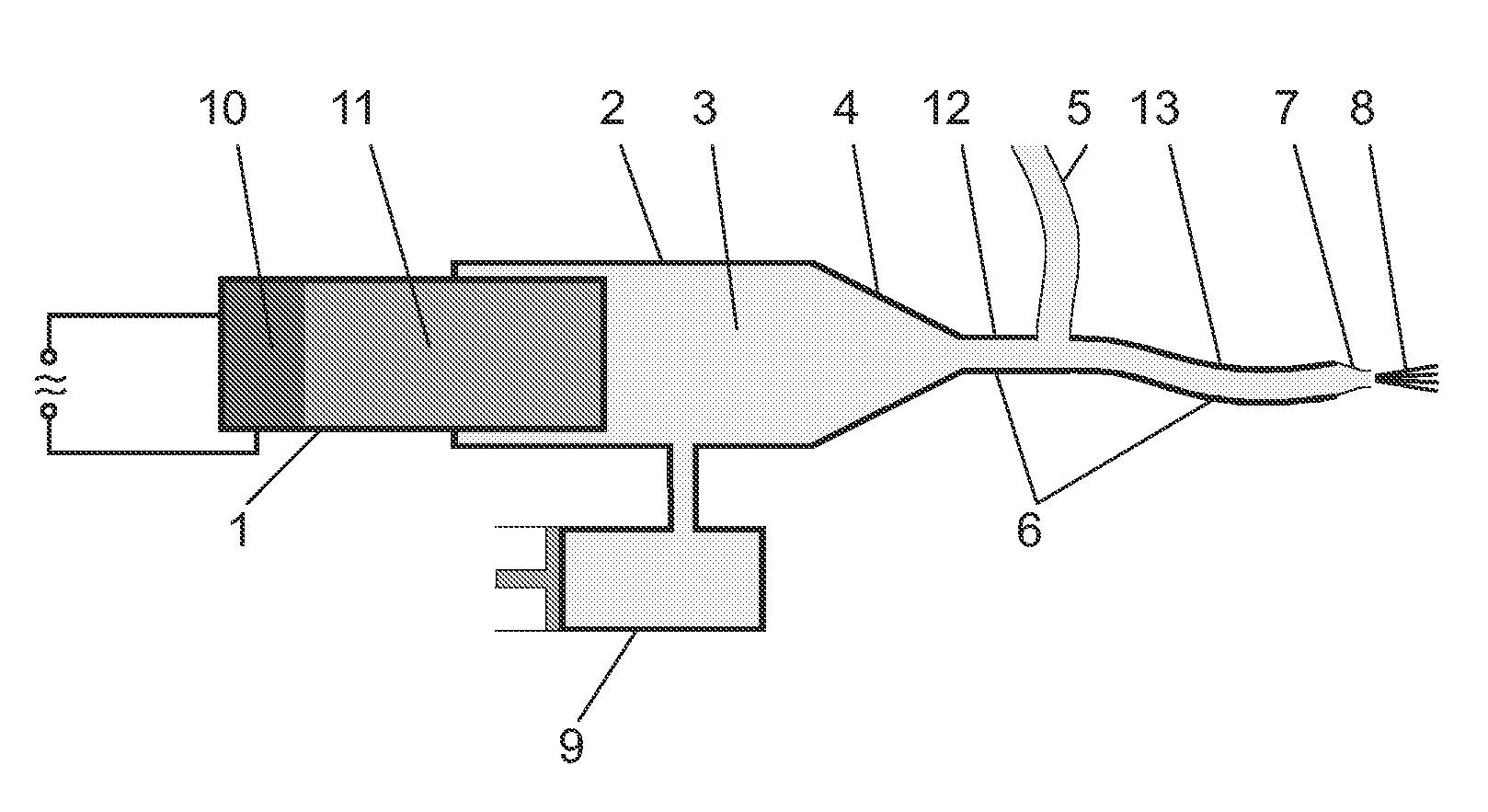
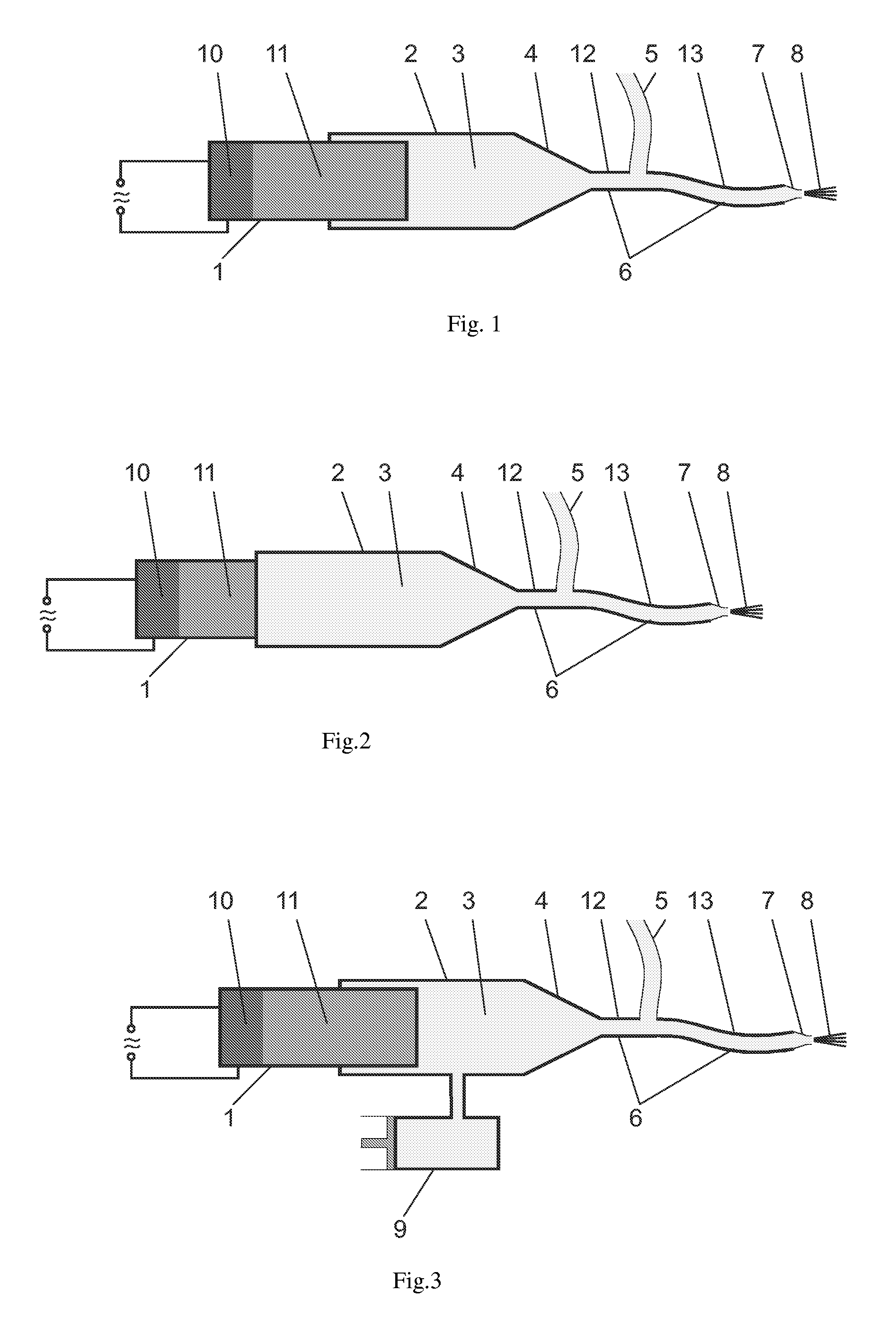
[0014]FIG. 1 is a schematic cross-sectional view of an apparatus for implementation of a method of generation of pressure pulsations for generating pulsating liquid jets according to the present invention utilizing direct action of an acoustic actuator on the pressure liquid in the acoustic chamber. Acoustic actuator 1, consisting of piezoelectric transducer 10 and cylindrical waveguide 11, transforms supplied electric power into mechanical vibration. Cylindrical waveguide 11 with diameter of 38 mm inserted into the cylindrical acoustic chamber 2 with diameter of 40 mm and filled with pressure liquid 3 transmits mechanical vibration into the liquid. As a result, pressure pulsations are generated in the pressure liquid 3. Pressure pulsations of the liquid are amplified in mechanical amplifier of pulsations 4 in the shape of cone frustum and transposed into the flowing pressure liquid at the point of connection to the pressure distribution 5 of the apparatus for application of liquid ...

example 2

[0015]FIG. 2 is a schematic cross-sectional view of an apparatus for implementation of a method of generation of pressure pulsations for generating pulsating liquid jets according to the present invention utilizing indirect action of an acoustic actuator on the pressure liquid in the acoustic chamber via the wall of the acoustic chamber. Acoustic actuator 1, consisting of piezoelectric transducer 10 and cylindrical waveguide 11, transforms supplied electric power into mechanical vibration. Cylindrical waveguide 11 with diameter of 38 mm is fixed to the wall of the cylindrical acoustic chamber 2 with diameter of 40 mm and filled with pressure liquid 3. Mechanical vibration of cylindrical waveguide 11 oscillates the wall of the cylindrical acoustic chamber 2 that transmits the oscillations into the pressure liquid 3. As a result, pressure pulsations are generated in the pressure liquid 3. Pressure pulsations of the liquid are amplified in mechanical amplifier of pulsations 4 in the sh...

example 3

[0016]FIG. 3 is a schematic cross-sectional view of an apparatus for implementation of a method of generation of pressure pulsations for generating pulsating liquid jets according to the present invention utilizing direct action of an acoustic actuator on the pressure liquid in the acoustic chamber equipped with a tuneable resonant chamber. Acoustic actuator 1, consisting of piezoelectric transducer 10 and cylindrical waveguide 11, transforms supplied electric power into mechanical vibration. Cylindrical waveguide 11 with diameter of 38 mm inserted into the cylindrical acoustic chamber 2 with diameter of 40 mm and filled with pressure liquid 3 transmits mechanical vibration into the liquid. As a result, pressure pulsations are generated in the pressure liquid 3. Acoustic chamber 2 is connected with a tuneable resonant chamber 9 that serves for matching of natural frequency of the acoustic system to the driving frequency of pressure pulsations. Pressure pulsations of the liquid are a...


PUM

PropertyMeasurementUnit
diameteraaaaaaaaaa
diameteraaaaaaaaaa
resonant natural frequencyaaaaaaaaaa

Abstract

An acoustic generator of pressure pulsations includes a cylindrical waveguide which is caused to vibrate at a low amplitude by an electromechanical transducer. The vibration of the cylindrical waveguide creates low amplitude pressure pulsations in an acoustic chamber containing stationary pressure fluid. A mechanical amplifier, which is part of the acoustic chamber, amplifies the low amplitude pressure pulsations generated by the cylindrical waveguide.

Description

TECHNICAL FIELD[0001]The present invention relates to a method of generation of pressure pulsations for generating pulsating liquid jets and an apparatus for implementation of the method.BACKGROUND ART[0002]Continuous liquid jets are commonly used for cutting and disintegration of various materials, for cleaning and removal of surface layers and coatings. Generating of sufficiently high pressure pulsations in pressure liquid upstream from the nozzle exit (so called modulation) enables to generate a pulsating liquid jet that emerges from the nozzle as a continuous liquid jet and it not forms into pulses until certain standoff distance from the nozzle exit. The advantage of such a pulsating jet compared to the continuous one consists in fact that the initial impact of pulses of pulsating jet on the target surface generates impact pressure that is several times higher than stagnation pressure generated by the impact of continuous jet under the same conditions. In addition, the impact o...

Claims


Application Information

Patent Timeline
Patent Type & Authority Patents(United States)
IPC IPC(8): B05B1/08G01N29/04G01N29/14
CPCB05B17/063B05B17/0607
Inventor FOLDYNA, JOSEFSVEHLA, BRANISLAV
Owner INST OF GEONICS ASCR
Why Eureka
Try Eureka