

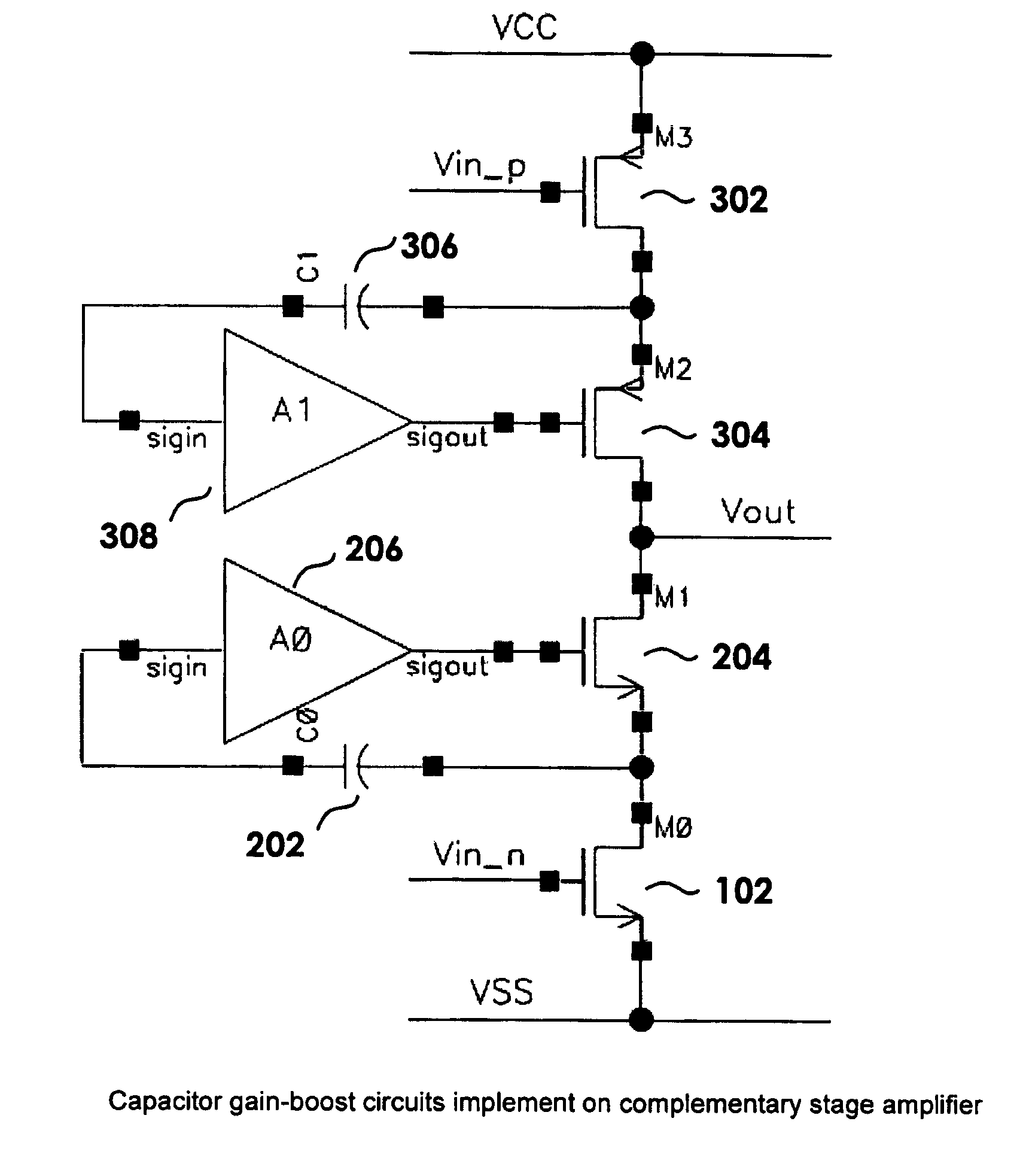
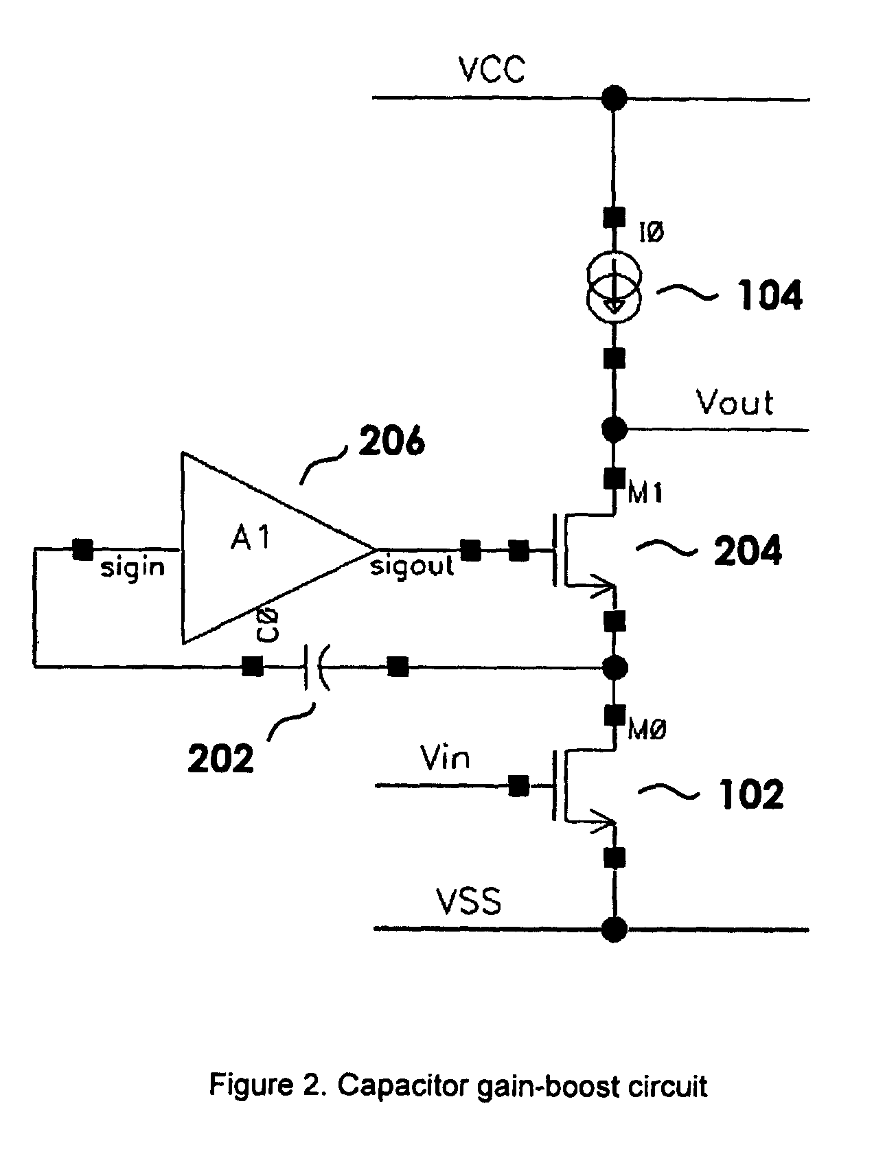
Capacitor gain-boost circuit
a capacitor gain and amplifier technology, applied in the field of integrated circuits, can solve the problems of limited system performance and design that has not been able to meet the increasing demand for high performance, and achieve the effect of wide supply voltage range and high gain
- Summary
- Abstract
- Description
- Claims
- Application Information
AI Technical Summary
Benefits of technology
Problems solved by technology
Method used
Image

Examples
Embodiment Construction
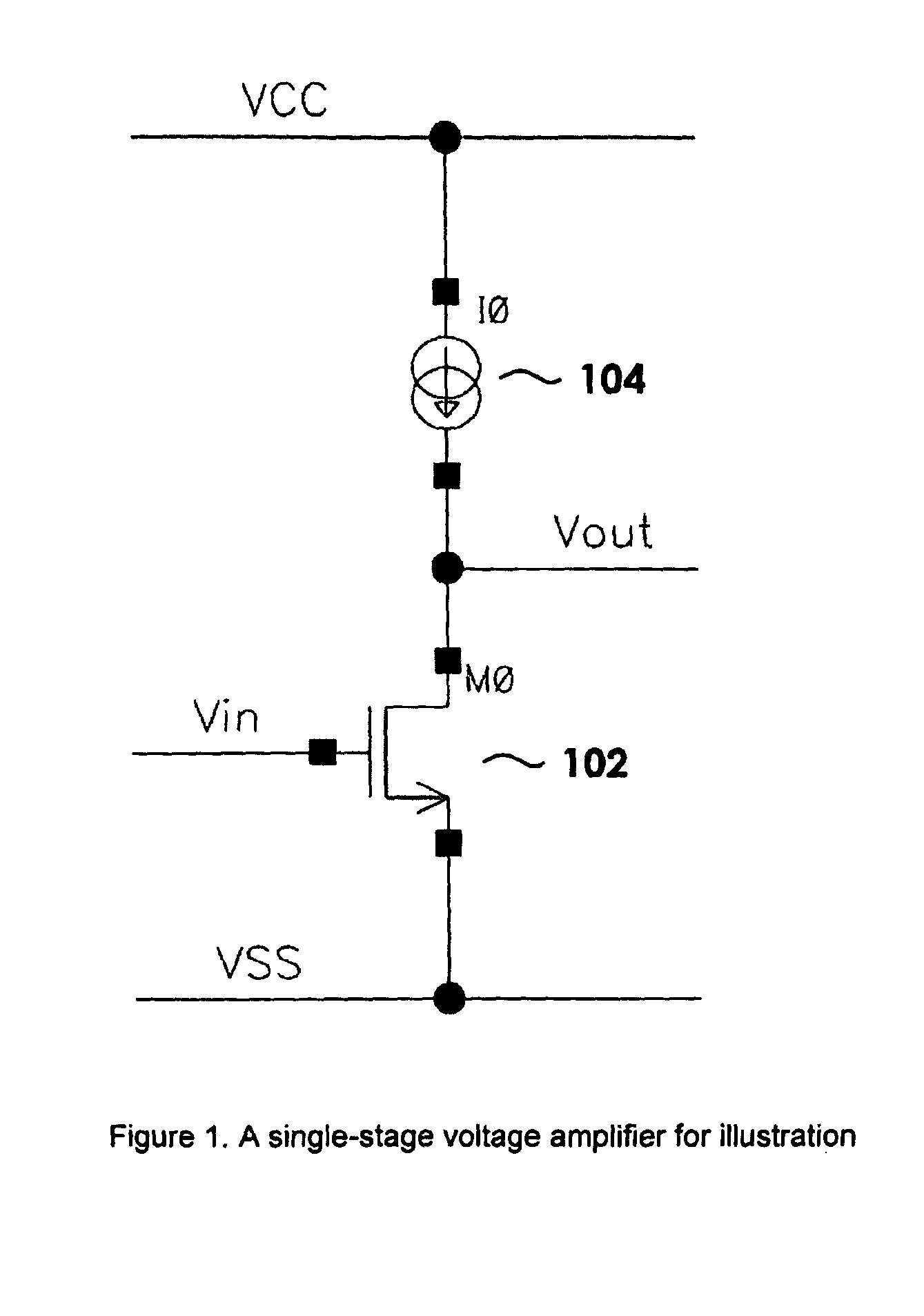
[0020]The present invention relates generally to integrated circuits and more specifically to analog amplifier circuits utilized in such circuits. The following description is presented to enable one of ordinary skill in the art to make and use the invention and is provided in the context of a patent application and its requirements. Various modifications to the preferred embodiment and the generic principles and features described herein will be readily apparent to those skilled in the art. Thus, the present invention is not intended to be limited to the embodiment shown but is to be accorded the widest scope consistent with the principles and features described herein.
[0021]A capacitor gain-boost circuit applied to an analog amplifier is disclosed. The capacitor gain-boost circuit can be configured to increase the gain of the amplifier. To describe the features of the present invention in more detail, refer now to the following description in conjunction with the accompanying Figu...
PUM
 Abstract
Description
Claims
Application Information