
Torsional resonator and filter using this

a torsional resonator and filter technology, applied in the direction of generators/motors, electrical apparatus, electrostatic generators/motors, etc., can solve the problems of difficult to form a minute mechanical vibration filter in the semiconductor process, difficult to detect beam displacement, and lessen the amount of beam displacemen

Active Publication Date: 2010-06-22
PANASONIC CORP +1
View PDF4 Cites 10 Cited by
  • Summary
  • Abstract
  • Description
  • Claims
  • Application Information

AI Technical Summary

Benefits of technology

[0037]According to the configuration of the torsional resonator of the invention, a filter that has a high Q value and can be used in a band of several hundred MHz to several GHz can be provided.

Problems solved by technology

In the described configuration, however, to form a filter of a higher frequency band, the following restriction exists: It is obvious from (expression 1) that it is desirable that first the material should be changed for increasing E / ρ, but if E is increased, the beam displacement amount lessens if the beam deflecting force is the same, and it becomes difficult to detect beam displacement.
In this case, it becomes difficult to form a minute mechanical vibration filter in a semiconductor process.
However, increasing the beam thickness h and lessening the beam length L lead to lessening the index of the ease of flexure, d / L in (expression 2), and it becomes difficult to detect beam flexure.
However, generally as the dimensions are miniaturized, the mechanical Q value of flexural vibration lowers; this is a problem.
Therefore, if the resonator using flexural vibration in the related art is miniaturized and is applied to a filter, the Q value required for providing a desirable frequency selection characteristic may be unable to be obtained.

Method used


Image

  • Torsional resonator and filter using this
  • Torsional resonator and filter using this
  • Torsional resonator and filter using this

Examples


first embodiment

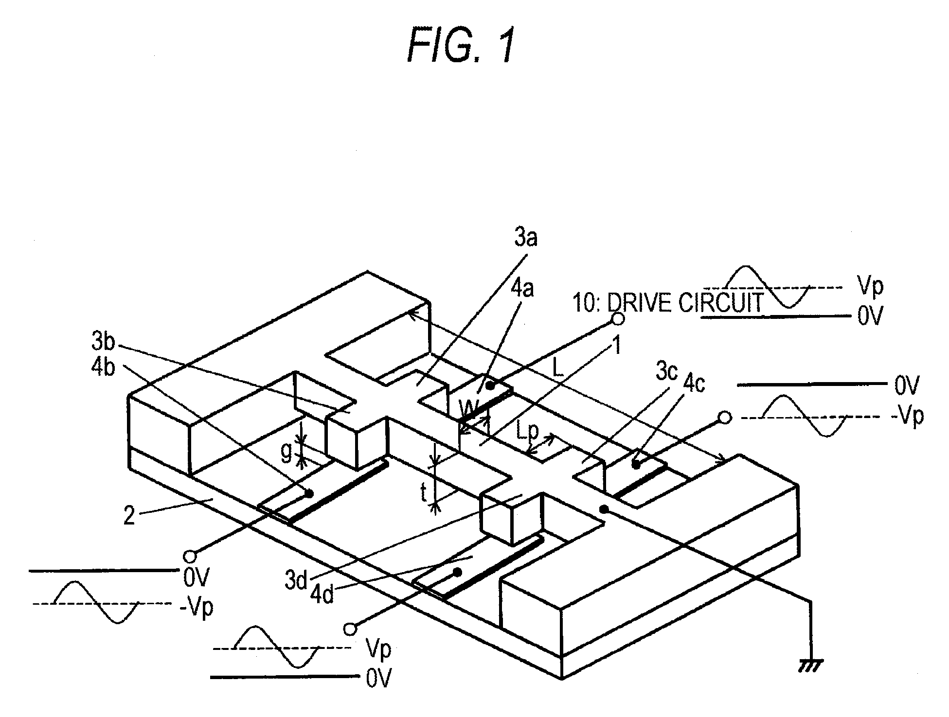
[0082]FIG. 1 is a perspective view of a torsional resonator in a first embodiment of the invention. The torsional resonator of the first embodiment is an electromechanical resonator having a vibrator 1 having paddle-like projections 3a, 3b, 3c, and 3d at axially symmetric positions for executing mechanical vibration and electrodes 4a, 4b, 4c, and 4d placed close to the paddle-like projections 3a, 3b, 3c, and 3d and having an electromechanical conversion function of converting voltage change between the paddle-like projections 3a, 3b, 3c, and 3d and the electrodes 4a, 4b, 4c, and 4d corresponding thereto into vibration of the vibrator, characterized by drive means configured so that an electrostatic force produced due to the potential difference between the electrode 4a, 4b, 4c, 4d and the vibrator produces a moment with the axis of a beam structure of the vibrator 1 as the center axis.

[0083]The vibrator 1 is a clamped-clamped beam fixed at both ends. The vibrator 1 is provided with ...

second embodiment

[0109]Next, a second embodiment of the invention will be discussed.

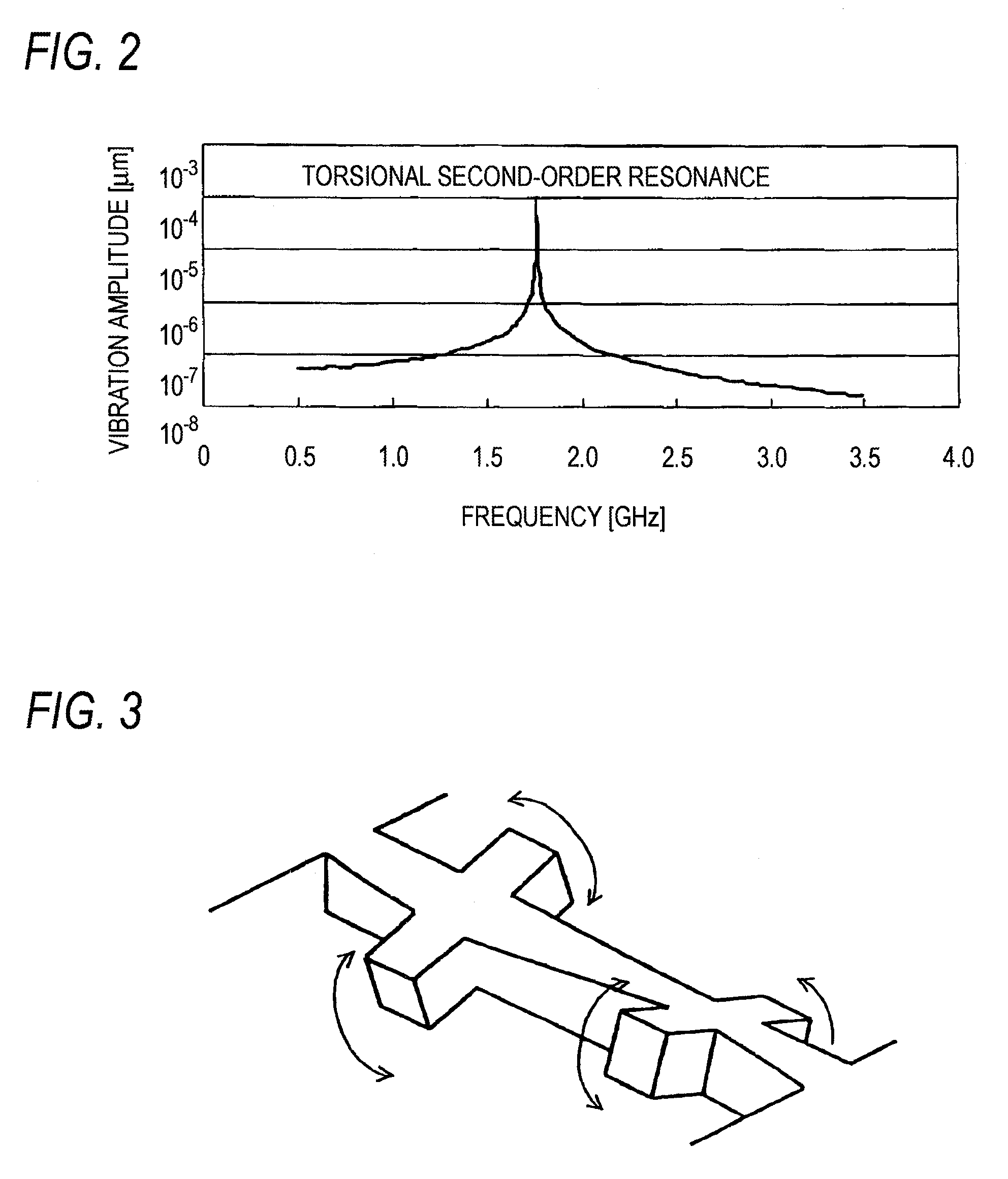
[0110]FIG. 13 is a block diagram of a circuit for exciting a torsional resonator in a second embodiment of the invention. Placement of a vibrator and electrodes is similar to that in FIG. 1 shown in the first embodiment, but an input signal is divided into four signals by a power splitter 11 and the bias voltages applied to electrodes 4a to 4d can be set in the range of −Vp to Vp. The amplitude spectrum of the vibrator when the bias voltage Vp is applied to the electrodes 4a and 4d and the bias voltage −Vp is applied to the electrodes 4b and 4c has only torsional second-order resonance as shown in FIG. 2. However, the bias voltage to the electrodes 4a and 4c is switched to Vp and the bias voltage to the electrodes 4b and 4d is switched to −Vp, whereby the amplitude spectrum of the vibrator 1 can be changed to that having only torsional first-order resonance as shown in FIG. 14. That is, as the bias voltages are switc...

third embodiment

[0115]Next, a third embodiment of the invention will be discussed.

[0116]In the first and second embodiments described above, adjustment is made using the power splitter so as to shift the phase of the voltage applied to each electrode; the third embodiment is characterized by the fact that the DC bias voltages applied to electrodes 4a to 4d are set to the same magnitude and the electrodes are placed in axially symmetric directions with respect to a beam 1 so that an electrostatic force is applied in the torsion direction of the beam 1 of a vibrator, as shown in FIGS. 16(a) and 16(b). That is, the electrodes are placed in the torsion direction relative to the vibrator so as to become equal in distance from the vibrator with torsional vibration of the beam 1 of the vibrator to form electrode pairs. Drive means applies the same AC signal and the same DC bias voltage to the electrode pairs with torsional vibration of the vibrator. Other points are similar to those of the first embodimen...


PUM


Abstract

A torsional resonator for suppressing unnecessary flexural vibration and providing excellent resonance characteristic is provided. A vibrator is a beam structure or a paddle-like projection structure added onto a beam structure and an electrostatic force produced due to the potential difference between an electrode and the vibrator adds a moment with the axis of the beam of the vibrator as the center axis, but does not add a force for producing flexure to the beam. As one method, the same AC signal and DC bias voltages different in polarity are applied to an electrode pair of the electrode brought away from the vibrator and the electrode brought close to the vibrator with torsional vibration of the vibrator, so that only torsional vibration can be excited.

Description

TECHNICAL FIELD[0001]This invention relates to a torsional resonator and a filter using the same and in particular to an art of realizing a high-performance filter circuit using torsional resonance in an electric circuit integrated at a high density.BACKGROUND ART[0002]A mechanical resonator in a related art will be discussed with reference to FIG. 18. FIG. 18 is a drawing to schematically show the configuration of a “mechanical vibration filter using flexural vibration” introduced in non-patent document 1.[0003]The filter is formed by forming a pattern on a silicon substrate using a thin film process, and is made up of an input line 104, an output line 105, clamped-clamped beams 101 and 102 placed with a gap of 1 micron or less relative to the lines, and a coupling beams 103 for coupling the two beams. A signal input from the input line 104 is capacitively coupled with the beam 101, generating an electrostatic force on the beam 101. Only when the signal frequency matches a frequenc...

Claims


Application Information

Patent Timeline
Patent Type & Authority Patents(United States)
IPC IPC(8): H03H9/125H03H9/52
CPCH03H3/0076H03H9/02259H03H9/2463H03H9/02433H03H2009/02519
Inventor NAKAMURA, KUNIHIKOKAWAKATSU, HIDEKI
Owner PANASONIC CORP
Learn More