Power plant with energy storage deep water tank

a technology of energy storage and power plants, applied in the direction of fluid couplings, clutches, couplings, etc., can solve the problem of large amount of energy stored

Inactive Publication Date: 2010-06-29
FLORIDA TURBINE TECH
View PDF4 Cites 56 Cited by
  • Summary
  • Abstract
  • Description
  • Claims
  • Application Information

AI Technical Summary

Benefits of technology

[0010]It is an object of the present invention to provide for an object of the present invention to provide for a power plant with the capability of storing energy during low demands periods for use during high demand periods so that the power plant does not have to be shut down or reduced in the power output.
[0012]The present invention is a power plant that includes an energy storage system that stores energy at low loads and releases energy at peak loads. The system includes a storage tank formed of steel reinforced concrete that is placed in a body of deep water. The storage tank is capable of withstanding the high pressure from the water depths. During the energy storage phase, compressed air is supplied to the storage tank to displace water from inside. When the stores energy is to be released, water from the deep is allowed to flow into the storage tank through a turbine to drive an electrical generator. Because the inside of the storage tank is at atmospheric pressure and the storage tank is in deep water, a high pressure gradient exists to drive the turbine. Because the storage tank is made from concrete, it is capable of withstanding the high pressure from the deep water in order to provide the relatively low pressure inside. Also, the storage tank can be easily fabricated such that a very large storage tank can be made. Thus, a large amount of energy can be stored for use at peak demand.

Problems solved by technology

Thus, a large amount of energy can be stored for use at peak demand.

Method used


Image

  • Power plant with energy storage deep water tank
  • Power plant with energy storage deep water tank

Examples


Embodiment Construction

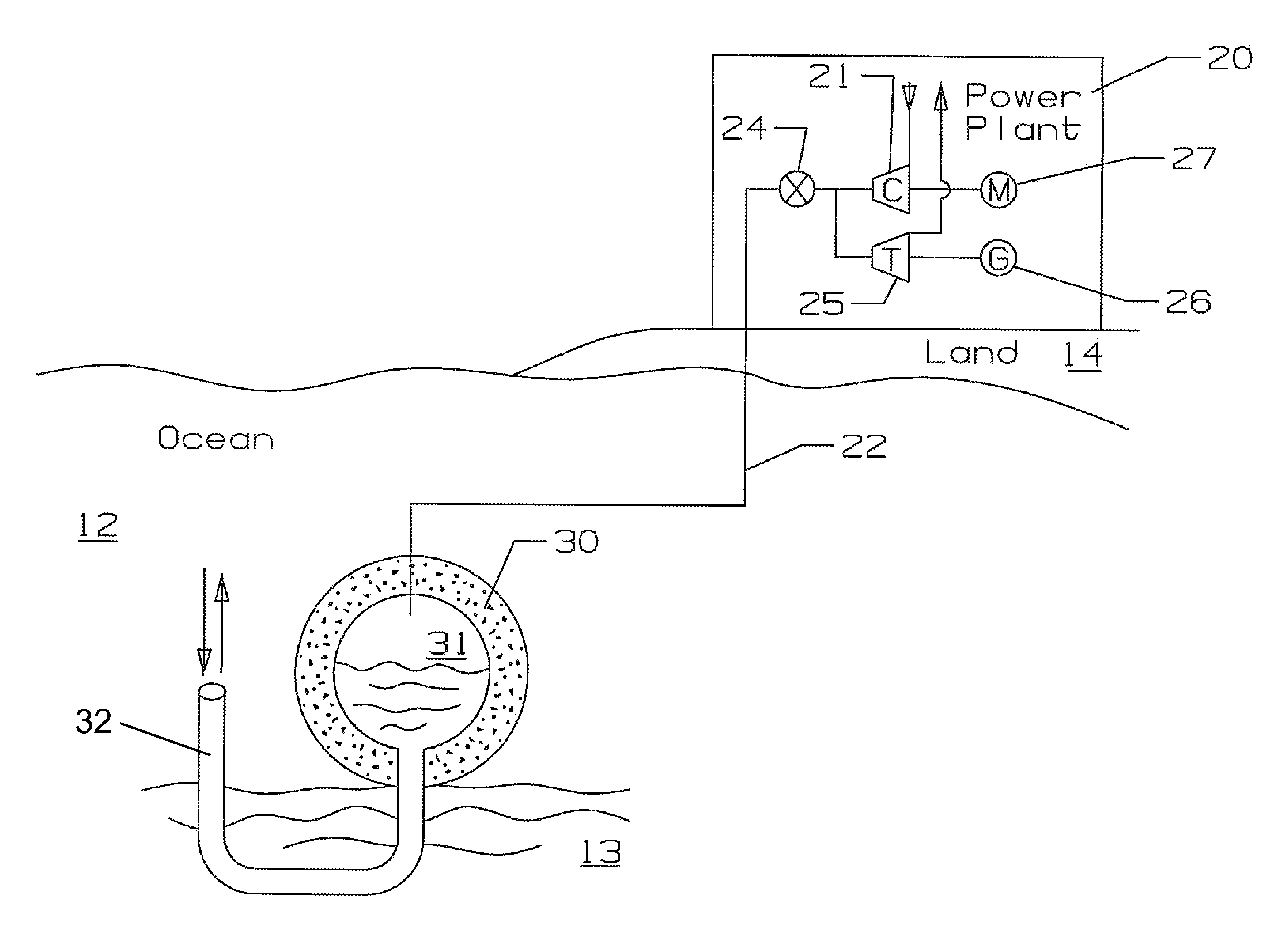
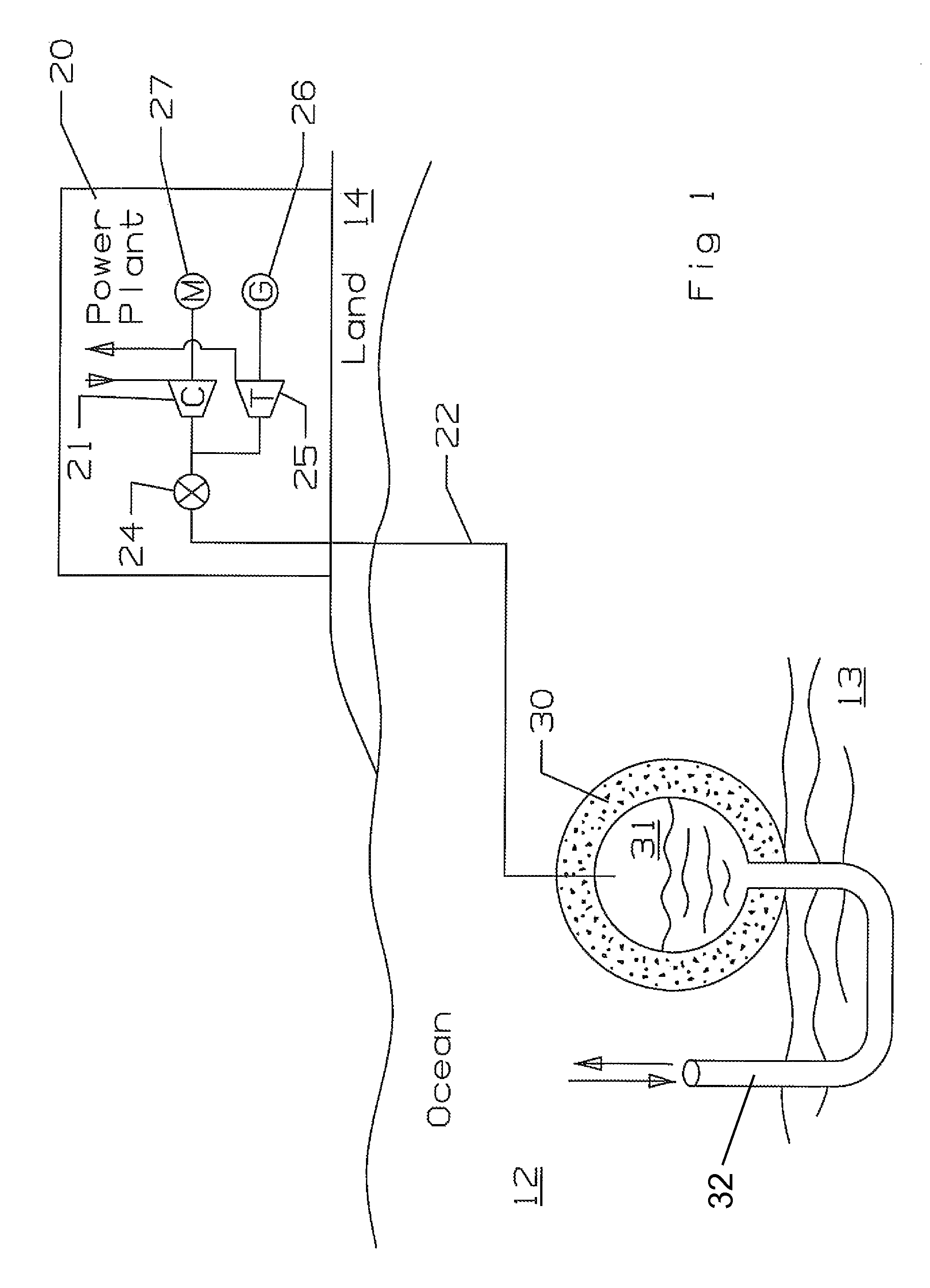
[0014]The power plant and energy storage system of the present invention is represented in FIG. 1. A power plant 20 for generating electricity is located on land 14. The energy storage system includes a storage reservoir 30 located on the bottom surface 13 of a body of water 12. The storage reservoir 30 is preferably made of concrete and reinforced by steel in order to allow for a relatively low pressure to exist inside the reservoir 30 under the influence of the high pressure from the body of water 12. Concrete can withstand very high compression forces. The storage reservoir 30 is preferably cylindrical in shape in order to withstand high compression forces.

[0015]The power plant drives an air compressor 21 connected to the reservoir 30 through a compressed air line 22. The tank 30 includes an inner space 31 and a water outlet pipe 32 connected at one end to the bottom of the concrete tank 30 and open on the opposite end into the body of water 12 near the tank 30 the compressed air...


PUM


Abstract

A power plant that is used for storing energy during a low demand and returning the energy to a power plant during high or peak demand. A concrete tank is placed on the bottom of a deep body of water. A compressed air line connects the tank to a compressor and turbine assembly on land at the power plant. An electric motor drives the compressor to supply compressed air to the tank and displace the water within the tank during the low demand period. At high demand, the compressed air is allowed to flow through the turbine that drives an electric generator to produce electric power. The tank includes a water outlet pipe for the tank is displaced of the high pressure water and to allow the water to flow into the tank and displace the compressed air under high pressure to drive the turbine.

Description

FEDERAL RESEARCH STATEMENT[0001]None.CROSS-REFERENCE TO RELATED APPLICATIONS[0002]This application is related to a co-pending U.S. regular utility application Ser. No. 12 / 026,571 filed on 6 Feb. 2008 and entitled POWER PLANT WITH ENERGY STORAGE DEEP WATER TANK.BACKGROUND OF THE INVENTION[0003]1. Field of the Invention[0004]The present invention relates generally to power plants, and more specifically to an energy storage tank for storing of energy in a deep water environment.[0005]2. Description of the Related Art including information disclosed under 37 CFR 1.97 and 1.98[0006]An electrical generating power plant for a city produces power in a turbine to provide electricity to various places. During a hot summer day, the demand for electrical power can be greater than the power plant is able to produce. During night, the demand for electrical power could be lower than the minimum electrical power that the plant is producing without shutting down. In the case of a nuclear power plant...

Claims


Application Information

Patent Timeline
Patent Type & Authority Patents(United States)
IPC IPC(8): F16D31/02
CPCF02C6/16Y02E60/15Y02E60/16
Inventor BROSTMEYER, JOSEPH
Owner FLORIDA TURBINE TECH
Why Eureka
Try Eureka