Microfluidic devices and methods facilitating high-throughput, on-chip detection and separation techniques

a microfluidic device and microfluidic technology, applied in the field of high-throughput microfluidic devices and methods, can solve the problems of complex sample itself, large dynamic range of proteins present, and difficult analysis of proteomic samples, etc., to achieve fast sample separation, improve high-throughput analysis, and fast sample separation

Inactive Publication Date: 2010-06-29
VIRGINIA TECH INTPROP INC
View PDF9 Cites 32 Cited by
  • Summary
  • Abstract
  • Description
  • Claims
  • Application Information

AI Technical Summary

Benefits of technology

[0016]The present invention provides microfluidic devices and methods for on-chip complex sample processing. As disclosed herein, “device” refers to a platform or chip (e.g., microchip) for microfluidic analysis. “Complex sample” refers to any biological and / or chemical sample and may include samples such as tissue, blood, cerebrospinal fluid, saliva, urine, etc. The complex sample may comprise any number or combinations of substances, including, but not limited to, polyamino acids (e.g., peptides, polypeptides, proteins), polynucleotides (e.g., nucleic acids), sugars (e.g., polysaccharides), other biological and chemical macromolecules or complexes, and more simple substances, such as metabolic precursors and products, vitamins, co-factors, lipids, and other substances that can be found in environments comprising living organisms. Other non-limiting examples include organic compounds. Generally speaking, the device comprises several parts including: a separation channel of a complex sample separation system; an array of microreservoirs flanking the separation channel to one side; and an interface for transferring the separated sample components from the separation channel to the microreservoirs. According to one aspect, the interface serves to orthogonally transfer the separated components into the array of microreservoirs. In addition, the device may enable detection of separated components directly from the chip. Preferably, the device: 1) provides for the separation of a complex mixture into components; 2) orthogonally transfers the separated components into an array of microreservoirs via an interface; 3) enables on-chip detection of separated components; and / or 4) provides for multiplexed and / or parallel processing, thereby facilitating high-throughput investigations.
[0017]According to one embodiment, the device comprises a complex sample separation means, including at least a separation channel, for receiving a complex sample and separating it into components; and an interface means coupled to the separation means for orthogonally transferring the separated sample components into a collection means. In addition, at least the separation channel, interface means, and collection means are deposited within the same chip, facilitating analyte detection from the chip.

Problems solved by technology

The analysis of proteomic samples is very difficult, however, for a number of reasons.
Second, the sample itself is typically complex (5,000-10,000 different proteins may be expressed in a mammalian cell at any given time).
Third, the dynamic range of the proteins present is typically very large (1:106) and / or their presence easily obscured by other more highly abundant components.
Comparatively, 2D-PAGE is a relatively awkward and time consuming separation technique that utilizes a gel to separate proteins according to isoelectric point, or charge, in a first dimension, and according to molecular weight, or size, in a second dimension.
These approaches, however, are accompanied by numerous limitations that include: insufficient quantitative correlation between gene and protein expression level; complexity and lengthiness for analytical approaches that attempt comprehensive qualitative / quantitative proteomic profiling; and lack of sufficient sensitivity, specificity and reproducibility.
However, some challenges toward this end include developing simple, compact, and low cost devices with parallel processing capabilities that would enable high-throughput investigations.
First, the miniature format of these devices enables the manipulation of extremely small sample amounts and short analysis times, resulting in significantly reduced analysis costs.
Despite the advantages of microfluidic devices, very few have been successfully combined with MS analysis (refs 10-30).
However, the bottleneck of all these applications goes back to the sequential nature of traditional ESI-MS detection.
Although the above microfluidic devices have demonstrated noteworthy sensitivity, throughput, and flexibility, they do not demonstrate the full benefits of microfluidic platforms combined with MS detection for a number of reasons.
First, as mentioned, the main limitation of ESI-MS detection in the context of microfabricated analysis platforms relates to the traditionally sequential nature of the technique.
Also, the fabrication of microfabricated ESI spray emitters is difficult, and their integration with microfluidic chips that perform complex sample processing steps has not been demonstrated.
Second, the fabrication of piezo-actuated micro-dispensers that enable sample collection from multiplexed microfluidic chips for MALDI-MS detection is not simple, and their integration within sample processing chips has not been demonstrated either.
Moreover, the dispensing process would deposit the sample onto a different chip than the one used for analysis, consequently increasing labor and costs.
Third, the centrifugal CD does not enable the integration of a separation step prior to MS analysis since sample collection occurs in a single spot.
Fourth, intense scrutiny of the SELDI chip approach has demonstrated that the technique is neither sufficiently reproducible, nor sensitive enough to detect low abundance signature biomarker components (ref 34).
Also, the technique does not enable dynamic processing of biological samples as required for protein analysis.
Such techniques do not provide sufficient throughput and cost-effective analysis.

Method used


Image

  • Microfluidic devices and methods facilitating high-throughput, on-chip detection and separation techniques
  • Microfluidic devices and methods facilitating high-throughput, on-chip detection and separation techniques
  • Microfluidic devices and methods facilitating high-throughput, on-chip detection and separation techniques

Examples


example 1

Microfluidic LC-MALDI Chips

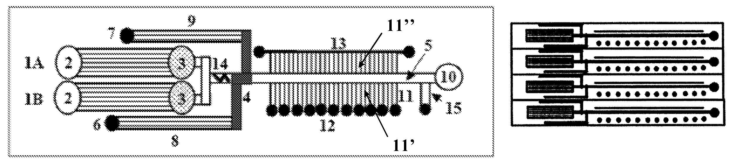
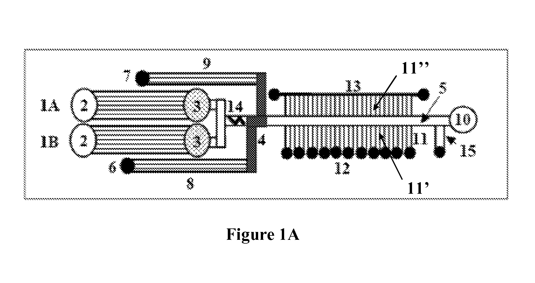
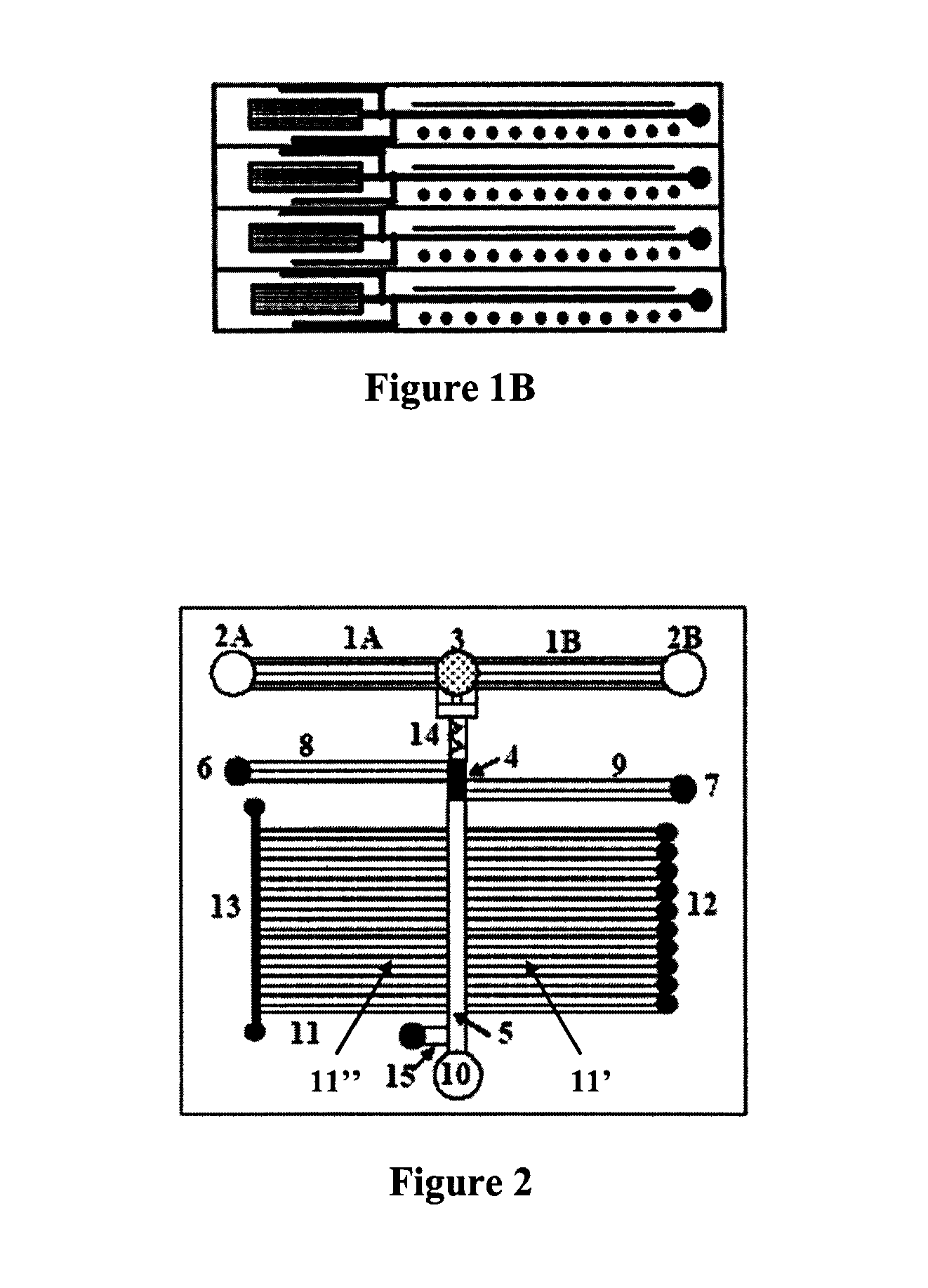
[0061]The first generation of microfluidic-MALDI chips was constructed and tested with fluorescent dyes. A region of an empty separation channel that is intersected by a multitude of 1.5 μm deep channels for MALDI sample collection is shown in FIG. 11A. In the present design, there are 10 microreservoirs for sample collection, the intersecting nanochannels are placed 50 μm apart, and each 2 mm section of the LC separation channel is connected through 40 nanochannels to a sample collection reservoir. Alternative designs may incorporate a large density of nanochannels that enable the connection of sub-millimeter separation channel regions to the MALDI reservoirs. FIG. 11B shows the microfluidic chip filled with a fluorescent dye. The elution of the LC separation channel content through the intersecting nanochannels into the MALDI reservoirs is shown in FIG. 11C. The chip was filled with a fluorescent dye solution and the sample rinse channel and collection r...


PUM

PropertyMeasurementUnit
depthaaaaaaaaaa
lengthaaaaaaaaaa
lengthaaaaaaaaaa

Abstract

The present invention provides a microfluidic device and method for facilitating on-chip complex sample processing and detection. In general, the device comprises at least a separation channel of a separation system, an interface, and an array of microreservoirs disposed within the same chip. The interface is configured to orthogonally transfer separated components from the separation channel into the array of microreservoirs, enabling direct analyte detection from the chip and high-throughput analysis.

Description

[0001]This invention was made with government support under Grant # BES0448840 awarded by the National Science Foundation. The government has certain rights in the invention.BACKGROUND OF THE INVENTION[0002]1. Field of the Invention[0003]The present invention generally relates to microfluidic devices and methods for use, and more particularly, to high-throughput microfluidic devices and methods for on-chip complex biological and / or chemical sample separation and / or detection of separated components.[0004]2. Discussion of Related Art[0005]Cancer is a leading cause of death in the U.S. and throughout the world, with over 1,000,000 new cases being diagnosed every year in the U.S. alone. Hundreds of genes are involved in the development of diseases such as cancer. An accumulation of mutations, which result in loss- or over-expression of genes that control cell growth and proliferation, ultimately lead to the onset of the disease. To fully elucidate the molecular mechanisms and pathways ...

Claims


Application Information

Patent Timeline
Patent Type & Authority Patents(United States)
IPC IPC(8): B01D15/08G01N30/02C02F1/28
CPCH01J49/04G01N2001/4038G01N2035/00237
Inventor LAZAR, IULIANA M.
Owner VIRGINIA TECH INTPROP INC
Why Eureka
Try Eureka