Method and device for the simultaneous coating and moulding of a body

a body and simultaneous technology, applied in the direction of dough shaping, cocoa, sweetmeats, etc., can solve the problems of not being able to produce any desired shape, not being able to use any apparatus known, and being unable to produce one hollow body, etc., to achieve the effect of reducing the thermal load on the substrate to be coated

Inactive Publication Date: 2010-06-29
SCHOTT AG
View PDF14 Cites 38 Cited by
  • Summary
  • Abstract
  • Description
  • Claims
  • Application Information

AI Technical Summary

Benefits of technology

[0026]According to one refinement of the invention, the HF AC voltage or the microwaves is / are introduced by means of an antenna positioned in the hollow body. In this way, a substantially cylinder-symmetrical field is generated in the hollow body. This allows a uniform coating to be produced.
[0027]Furthermore, it is preferable for the microwaves or high-frequency AC voltage to be pulsed. In this way, the thermal load on the substrate to be coated is reduced, and in particular gas exchange is made possible between the pulses, so that especially clean coatings can be produced using pulsed fields.
[0028]In yet a further refinement of the invention, the AC voltage introduced and / or the microwaves introduced is / are controlled in such a way that a coating is formed substantially only at the wall of the body, in accordance with the higher field intensity which is present there. This is possible with an antenna which is positioned in the center of the body with the field strength generated by the HF AC voltage decreasing in the radial direction. For example, the gas discharge can be controlled in such a way that a coating is formed only on the inner and / or outer side of the hollow body. This has the advantage that the installation is not contaminated by the coating.
[0029]In an expedient embodiment of the invention, the mold has at least one ejector element, which for its part includes a passage for the introduction of process gas and / or microwaves. Ejector elements are used in injection molding to eject the part which has been produced and may stick to the mold or holder. A passage through which process gas and / or microwaves can be introduced is provided at the ejector element according to the invention. This allows components which are required for the coating to be integrated in an existing component of an injection molding installation.

Problems solved by technology

A drawback of the apparatus which is known from WO 99 / 17334 is that it is in each case only possible to produce one hollow body per coating station.
A further drawback is that the apparatus which is known from WO 99 / 17334 cannot be used to produce bodies of any desired shape.

Method used


Image

  • Method and device for the simultaneous coating and moulding of a body
  • Method and device for the simultaneous coating and moulding of a body
  • Method and device for the simultaneous coating and moulding of a body

Examples


Embodiment Construction

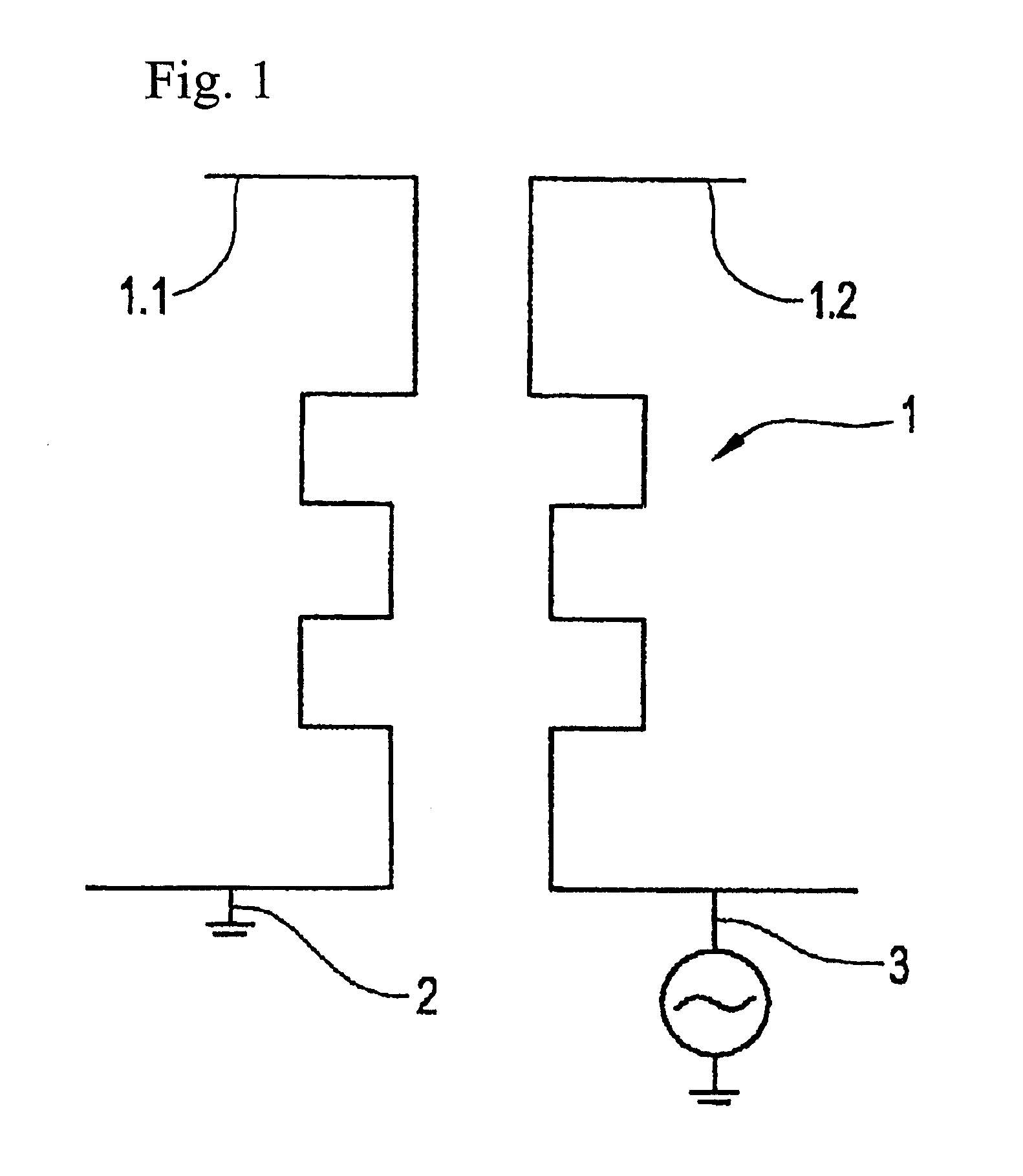
[0040]FIG. 1 shows a mold 1 according to the invention which comprises two mold halves 1.1 and 1.2. If, in one embodiment of the invention, to excite the plasma one mold half 1.1 of the mold is connected as an anode and ground potential 2 is applied, the other mold half is connected as a cathode, to which a high-frequency alternating field 3 can be applied.

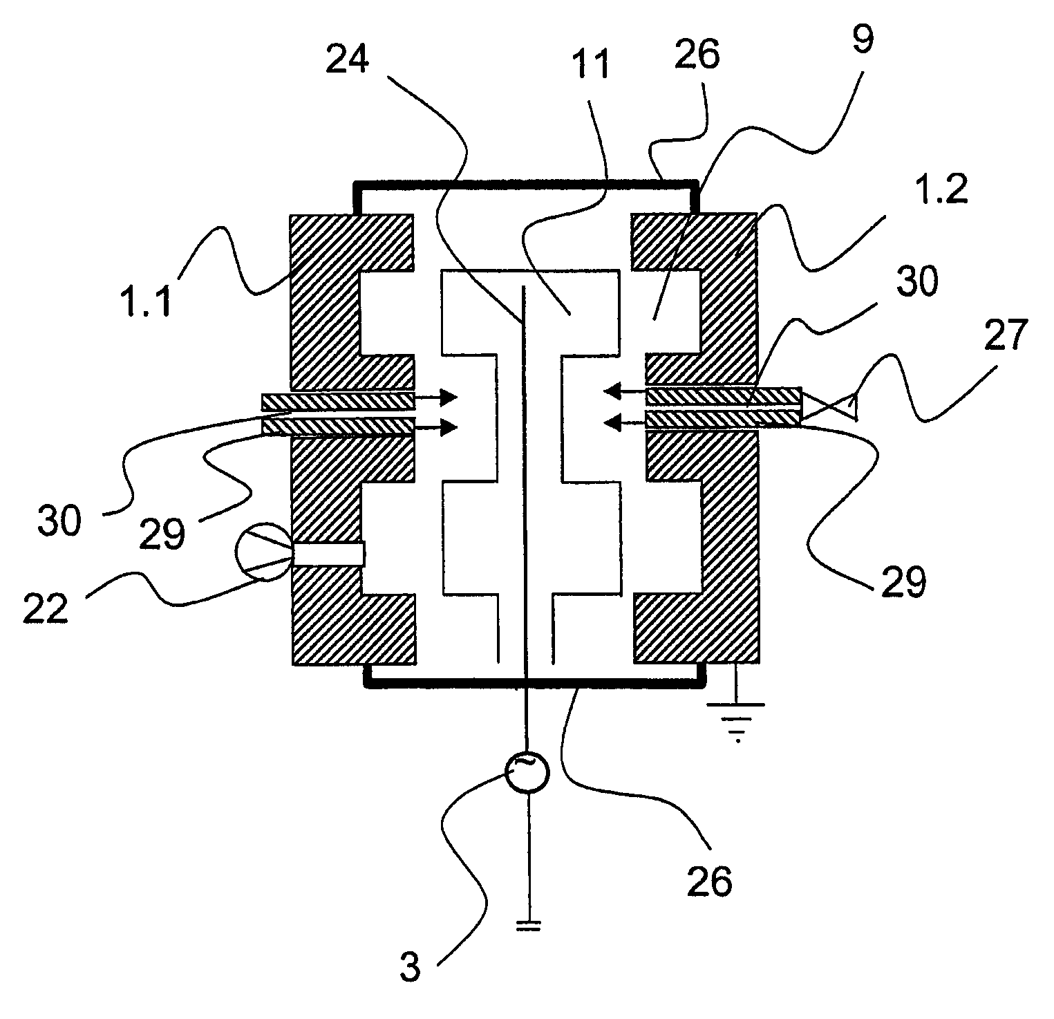
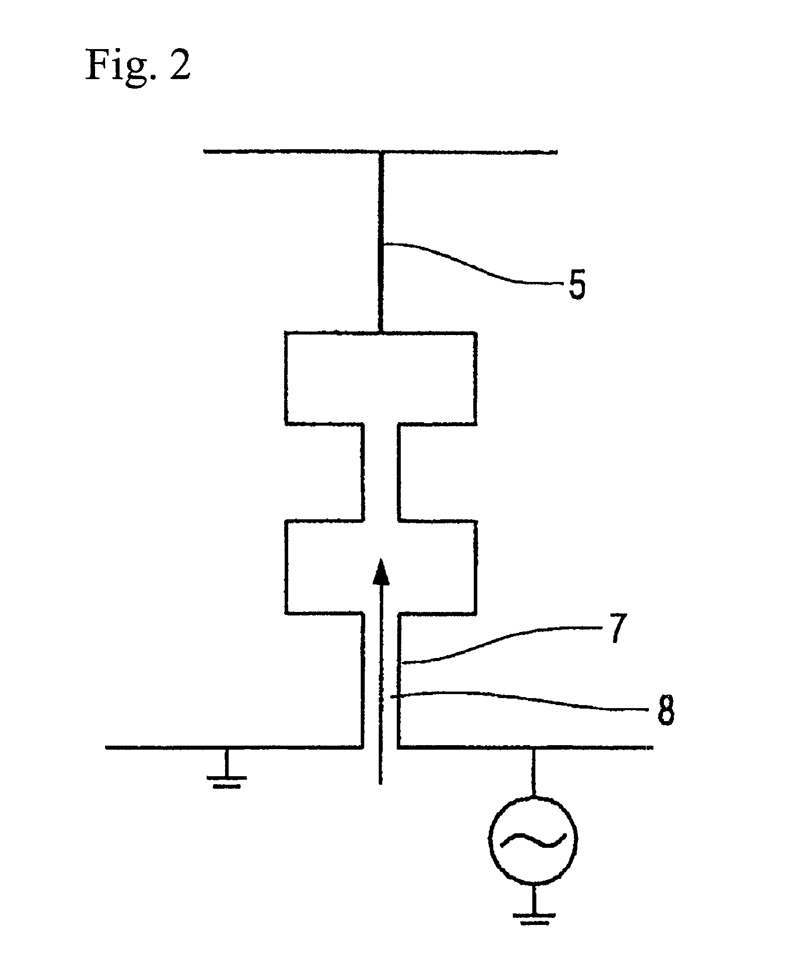
[0041]In a first process step, the two mold halves 1.1 and 1.2 are moved toward one another, so that they come into contact with one another in the upper region 5 and a passage 8, into which injection-molding material, for example a plastic material, such as polyethylene, etc., is introduced, is formed in the lower region 7 of the mold 1. To prevent a short circuit between the mold halves when an AC voltage is applied in order to generate a plasma, an electrical insulator material, such as for example mica, quartz or Teflon, is applied in the upper region 5 of the mold half in which the mold halves come into contact with one anoth...


PUM

PropertyMeasurementUnit
thicknessaaaaaaaaaa
thicknessaaaaaaaaaa
frequenciesaaaaaaaaaa

Abstract

A process for simultaneously coating and forming a body. The process includes moving two mold halves into contact with one another; introducing an injection-molding material into the mold halves so that a molding is formed; evacuating the molding; admitting a gas into the molding; igniting a plasma in the molding so that a coating is deposited on the inner side of the molding; and moving the mold halves apart so that the molding drops out.

Description

BACKGROUND OF THE INVENTION[0001]1. Field of the Invention[0002]The invention relates to a process and an apparatus for coating and forming a body and to a body produced thereby.[0003]2. Description of Related Art[0004]To reduce the permeation of gases and liquids in the field of plastic packaging and to protect the plastic material from chemical attack or UV radiation, it is advantageous for substrate materials, in particular three-dimensional hollow bodies, to be provided with a coating, in particular a barrier coating. Coatings allow the same property to be achieved with inexpensive bulk plastics as with expensive specialty plastics and make it possible to replace glass, for example, in the field of pharmaceutical packaging materials with bulk plastics of this type. Applications of coatings to a plastic substrate have been disclosed by the following applications:[0005]U.S. Pat. No. 5,798,139[0006]U.S. Pat. No. 5,833,752[0007]U.S. Pat. No. 6,001,429[0008]U.S. Pat. No. 5,798,139 de...

Claims


Application Information

Patent Timeline
Patent Type & Authority Patents(United States)
IPC IPC(8): B29C51/10B05D7/22B05D7/24B29C45/00B29C45/17
CPCB05D1/62B05D7/227B29C45/1703B29C45/0053B29C2045/0079
Inventor BEHLE, STEPHANKUHR, MARKUSWALTHER, MARTENWOLFF, DETLEFBICKER, MATTHIAS
Owner SCHOTT AG
Why Eureka
Try Eureka