
Monochromator and radiation source with monochromator

a radiation source and monochromator technology, applied in the field of monochromators, can solve the problems of increasing the interaction of charged particles, increasing the size of virtual sources, and impairing the resolution of optics, so as to improve the yield of charged particles and improve the ability to control and calculate fringe fields

Active Publication Date: 2010-06-29
CEOS CORRECTED ELECTRON OPTICAL SYST
View PDF9 Cites 2 Cited by
  • Summary
  • Abstract
  • Description
  • Claims
  • Application Information

AI Technical Summary

Benefits of technology

"The invention is about a new method for focusing charged particles in a microscope. The method uses a deflection element with a specific design to point-focus the desired energy interval of the particles in the area of the selection aperture. The charged particles are point-focalized in the plane of the selection aperture, which allows for the separation of the desired energy interval from the unwanted energy intervals. The method also includes a design for eliminating cross-talk and the Boersch effect, which can occur when using a slit aperture. The invention provides a more efficient and effective way to focus charged particles in a microscope."

Problems solved by technology

Chromatic aberration is one of the main factors that limits the resolution in the charged particle optics due to the resulting broadening of the charged particle beam due to the width of the energy spectrum and the chromatic aberration of the lenses.
One disadvantage of a monochromator of this construction is that the interaction of the charged particles increases the closer they are brought together.
The charged particles deflect each other, which causes deceleration and acceleration with an additional dispersion effect, which results in an increase of the virtual source size.
It can thereby reverse the displacements caused by its deflecting fields, but not those displacements caused by the interaction of the charged particles, which influences the monchromatism and thereby the ability of focusing the beam, which again impairs the resolution of the optics.
Since all previous monochromators show the disadvantageous Boersch effect of point focuses (stigmatic intermediate images), the beam current had to be limited to 10 nA (loc. cit.
8). This is again disadvantageous, since an increase in resolution requires large illumination currents in connection with a small source energy wi
This monochromator does avoid the strong Boersch effect of stigmatic intermediate images, but the disadvantage of this monochromator is that unevenness or soiling of the aperture slit also effects the charged particle beam, resulting in scattering and intensity modulations in the final image of the optical system which show up as stripes across the image (FIGS. 8a and 8b).
The sensitivity in this regard is sufficiently large that this fault cannot be prevented by mechanical precision and prevention of dirt deposit.
In particular, for objects with small intensity contrast such as thin crystals, this causes the intensity contrasts of the object to be superimposed by the intensity contrasts of this defect, which produces stripes in the image that often prevent image evaluation.

Method used


Image

  • Monochromator and radiation source with monochromator
  • Monochromator and radiation source with monochromator
  • Monochromator and radiation source with monochromator

Examples


Embodiment Construction

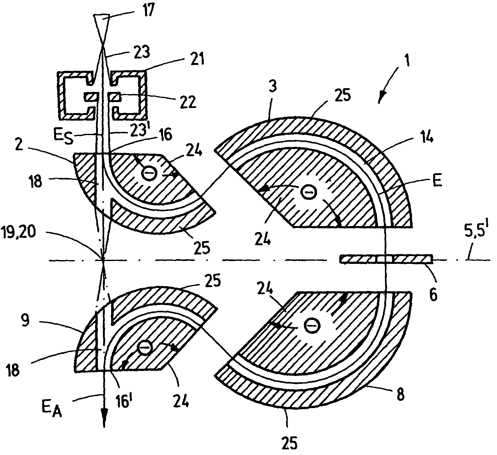
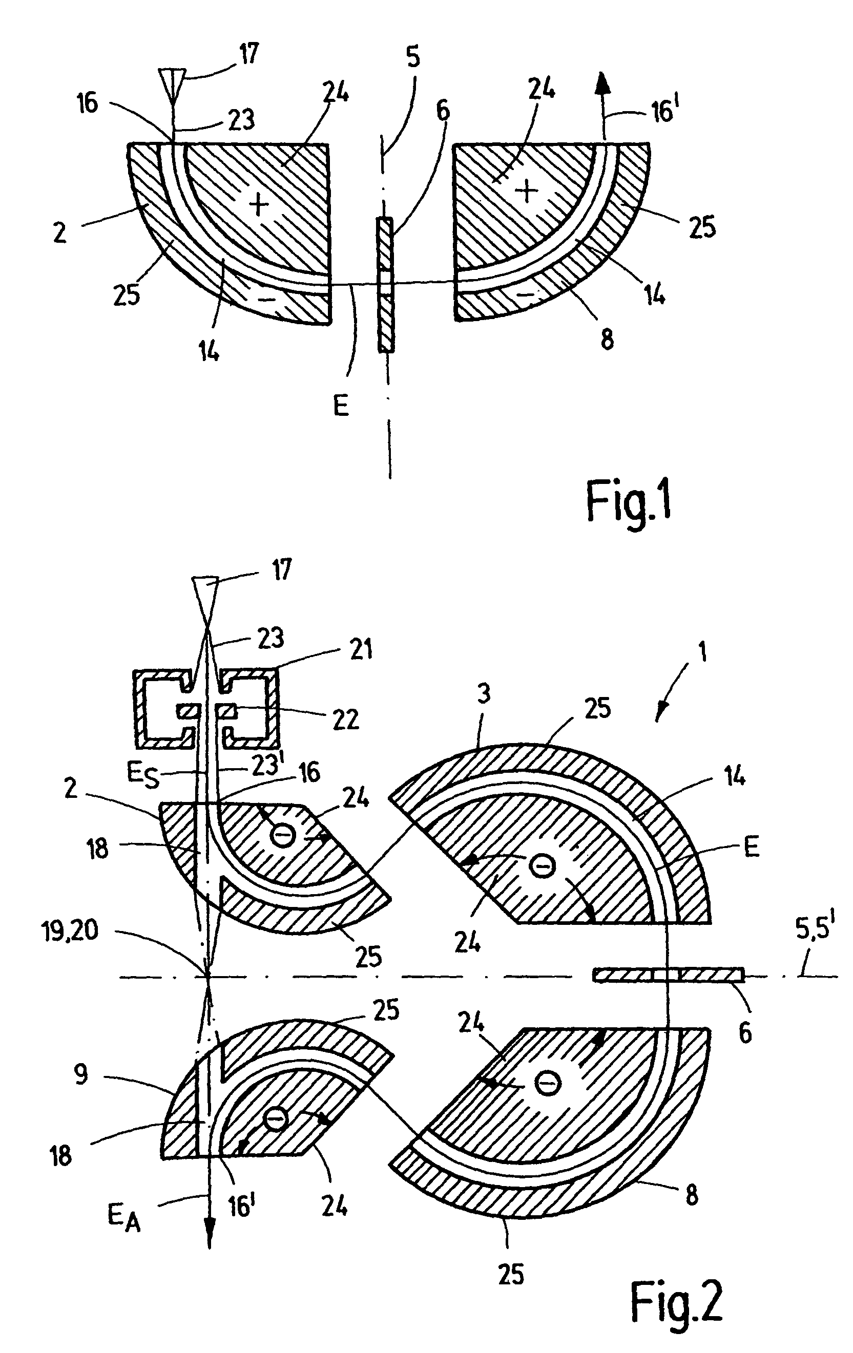
[0056]FIG. 1 shows a schematic diagram of an embodiment of a monochromator 1 having a simple construction in accordance with the invention. The particle current 23 of a radiation source 17 is thereby incident on the entry 16 of the monochromator 1 and is deflected by the deflecting field 2′ of a first deflection element 2 for generating a dispersion 4 (see below). This deflection is caused by an inner electrode 24 and an outer electrode 25 which delimit an arc-shaped deflection path 14. When the particle current 23 consists of electrons or negatively charged ions, the inner electrode 24 is positively charged and the outer electrode 25 is negatively charged. When the particle current 23 along the optical axis E of the monochromator 1, when deflected, is dispersely incident on the selection aperture 6 disposed in the plane 5, only the desired energy interval 7 is allowed to pass at that point, which is explained in more detail below. In order to eliminate again the dispersion 4, a fur...


PUM


Abstract

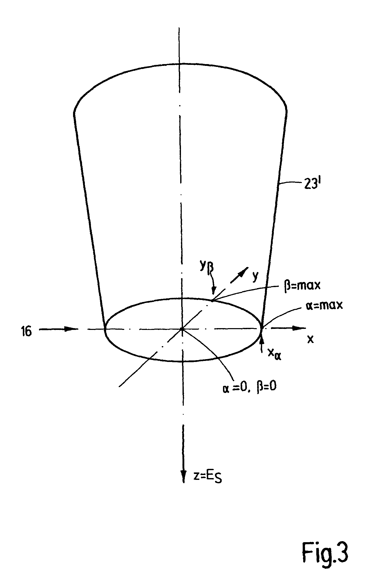
A monochromator (1) for a charged particle optics, in particular, for electron microscopy, comprises at least one first deflection element (2, 3) with an electrostatic deflecting field (2′, 3′) for generating a dispersion (4) in the plane (5) of a selection aperture (6) to select charged particles of a desired energy interval (7) and at least one second deflection element (8, 9) with an electrostatic deflecting field (8′, 9′) which eliminates the dispersion (4) of the at least one first deflecting field (2′, 3′). A radiation source (17) comprises such a monochromator (1). High monchromatism without intensity contrasts caused by defects of the slit aperture is thereby achieved in that the deflection elements (2, 3, 8, 9) have a design other than spherically shaped and their electrodes (24, 25) are given a potential (φ+, φ−) such that the charged particles (xα, yβ) which virtually enter the image of the radiation source (17) at different respective angles (α, β) in different sections (x, y), are differently focused such that charged particles (xα, yβ) of one energy are point focused (10, 10′, 10″) exclusively in the plane (5) of the selection aperture (6), since zero-crossings (11, 12) of the deflections (A) of the charged particles (xα, yβ) of the different sections (x, y) only coincide there at the same axial position (z, E).

Description

[0001]This application claims Paris Convention priority to DE 10 2007 024 353.9 filed on May 24, 2007 the entire disclosure of which is hereby incorporated by reference.BACKGROUND OF THE INVENTION[0002]The invention concerns a monochromator for a charged particle optics, in particular, for electron microscopy, comprising at least one first deflection element with an electrostatic deflecting field for generating a dispersion in the plane of a selection aperture for selecting the charged particles of the desired energy interval and at least one second deflection element with an electrostatic deflecting field which eliminates the dispersion of the at least one first deflecting field.[0003]Chromatic aberration is one of the main factors that limits the resolution in the charged particle optics due to the resulting broadening of the charged particle beam due to the width of the energy spectrum and the chromatic aberration of the lenses. The monochromators are used to limit this chromatic...

Claims


Application Information

Patent Timeline
Patent Type & Authority Patents(United States)
IPC IPC(8): G21K1/06G21K5/02
CPCH01J37/05H01J37/153H01J37/26H01J49/48H01J2237/1538H01J2237/057H01J2237/1534
Inventor UHLEMANN, STEPHAN
Owner CEOS CORRECTED ELECTRON OPTICAL SYST
Learn More