Insulating panel

a technology of insulating panels and panels, applied in the field of building insulation, can solve the problems of compromising reducing the efficiency of the panel, so as to achieve the effect of reducing the potential of conduction and convective heat transfer modes, increasing the thermal insulating capacity of the panel, and reducing the synergy of conduction and convection loss

Active Publication Date: 2010-07-06
SECCO INT
View PDF4 Cites 19 Cited by
  • Summary
  • Abstract
  • Description
  • Claims
  • Application Information

AI Technical Summary

Benefits of technology

[0015]Advantages of the present invention include that the proposed insulating panel is provided with at least two juxtaposed layers of cells extending transversely between the two environments between which the panel is located and which the panel attempts to thermally insulate. Hence, the thermal insulating capacity of the panel is increased to that of structures using a single layer of cells since both conduction and convective heat transfer modes are potentially reduced.
[0016]Also, in some embodiments of the invention, at least a portion of the material separating the two juxtaposed layers of cells is substantially infrared radiation reflective, which adds to the synergy of conduction and convection losses reduction by reducing radiation heat losses.
[0017]Furthermore, the proposed insulating panel is designed so that, should one or more of its cells be punctured, the panel is able to maintain its external structural integrity and, hence, remains able to extend across the opening it attempts to thermally insulate.
[0019]Yet, still, furthermore, the proposed insulating panel is designed so as to be manufacturable using conventional forms of manufacturing, hence providing an insulating panel that will be economically feasible, long-lasting and relatively trouble-free in operation.

Problems solved by technology

However, these relatively large windows are also unfortunately responsible for heat loss during cold winter nights and days due to re-radiation of the heat from the interior of the building through the windows to the colder air.
Although somewhat useful, conventional cellular window coverings structures however suffer from numerous drawbacks.
Also, because of the inherent construction of prior art cellular insulating panels, should a leak occur in any of the cells, the leak would compromise the efficiency of the panel altogether and potentially lead to its breakdown.
Furthermore, because of their inherent construction, these prior art cellular insulating panels are not well adapted to being only deflated in a predetermined region thereof so as to allow selective retraction of a portion thereof.

Method used


Image

  • Insulating panel
  • Insulating panel
  • Insulating panel

Examples


Embodiment Construction

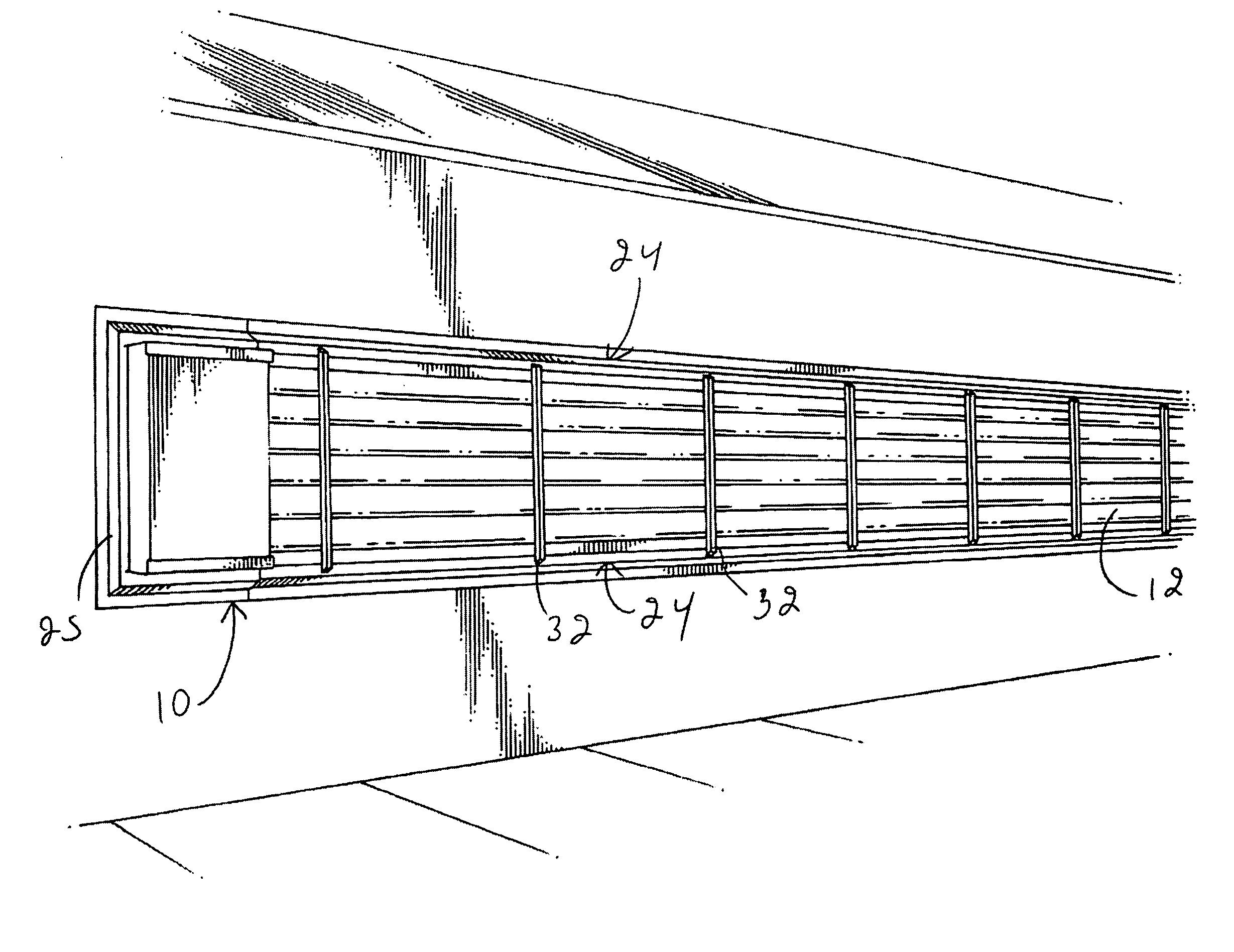
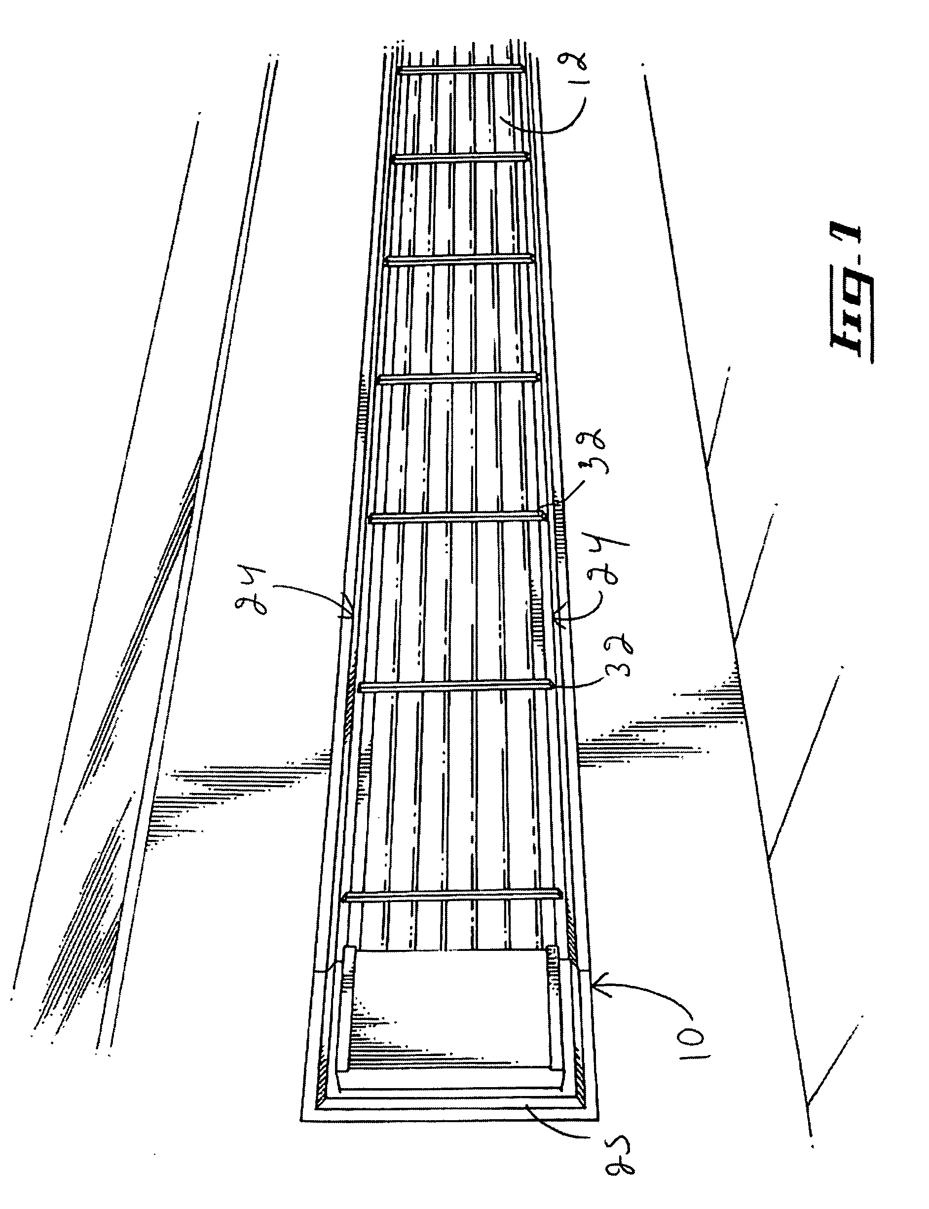
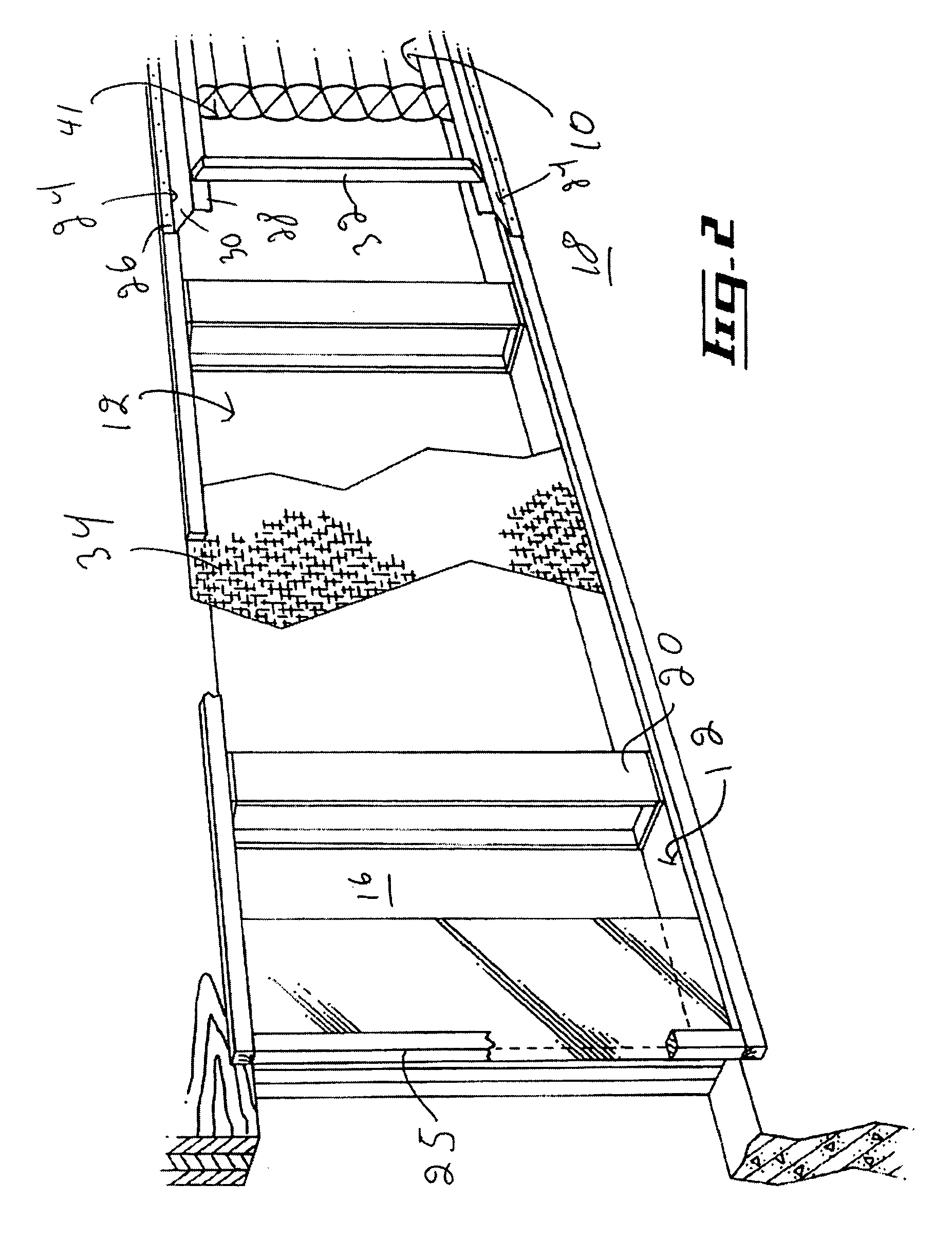
[0031]Referring to FIG. 1, there is shown an insulating panel in accordance with an embodiment of the present invention, generally indicated by the reference numeral 10. The insulating panel 10 is shown extending across a window aperture 12 defining an aperture plane extending substantially thereacross. As shown more specifically in FIG. 2, the window aperture 12 typically extends across a wall 14 such as a partition wall partitioning two rooms part of a building or an exterior wall delimiting the exterior of the building from its interior. It should, however, be understood that the insulating panel 10 could be used in other contexts for extending across other types of apertures of a building, such as for example doors or the like, without departing from the scope of the present invention.

[0032]The insulating panel 10 is typically used to thermally insulate two distinct environments. These two distinct environments are schematically referred to in FIG. 2 as a first environment 16 lo...


PUM

PropertyMeasurementUnit
membrane structureaaaaaaaaaa
heat lossaaaaaaaaaa
temperatureaaaaaaaaaa

Abstract

An insulating panel attachable to a building, the building defining a building aperture, the building aperture defining an aperture plane extending substantially thereacross. The insulating panel includes a membrane structure defining a first external wall and a substantially opposed second external wall; a peripheral wall extending between the first and second external walls, the first external wall, second external wall and peripheral wall together defining an enclosure; and an internal wall system located between the first and second external walls, the internal wall system being configured so as to divide the enclosure into a first cell located substantially adjacent to the first external wall and a second cell located substantially adjacent to the second external wall, the first and second cells being substantially spaced apart respectively from the second and first external walls by the internal wall system. A frame is attachable to the building, the frame being operatively coupled to the membrane structure for maintaining the first external wall substantially parallel to the aperture plane and substantially in register with at least a portion of the building aperture when the frame is attached to the building.

Description

FIELD OF THE INVENTION[0001]The present invention relates generally to the field of building insulation is particularly concerned with an insulating panel.BACKGROUND OF THE INVENTION[0002]With the advent of possible energy shortages and the ever-increasing costs of energy along with major concerns about the environment, there has been a concurrent renewed interest in energy conservation technology. A particular area or field where energy is often managed less than satisfactorily is that of heat gains and losses in both commercial and residential buildings through poorly insulated wall areas such as windows and the like.[0003]One of the basic tenants of conventional solar energy saving principles for buildings is that substantially large and south-facing windows can be used to gain heat during sunny winter days. However, these relatively large windows are also unfortunately responsible for heat loss during cold winter nights and days due to re-radiation of the heat from the interior ...

Claims


Application Information

Patent Timeline
Patent Type & Authority Patents(United States)
IPC IPC(8): E04B1/34E06B9/02
CPCE06B9/02E06B7/2318Y02B30/94Y02B30/90Y02A30/00
Inventor COTE, ERIC
Owner SECCO INT
Why Eureka
Try Eureka