Electrostatic coating spray gun

a spray gun and electrostatic technology, applied in the direction of electrostatic spraying apparatus, coatings, burners, etc., can solve the problems of large size of electrostatic spray gun, inability to electrify atomized coating material particles, and inability to bring about electric discharge between, so as to reduce the amount of coating material particles adhesion to the surface of the air cap

Inactive Publication Date: 2010-07-06
ASAHI SANAC KK
View PDF22 Cites 10 Cited by
  • Summary
  • Abstract
  • Description
  • Claims
  • Application Information

AI Technical Summary

Benefits of technology

[0006]The invention was made based from such backgrounds. It is therefore an object of the invention to provide an air spray type electrostatic coating spray gun that can be used for electrostatic coating using an aqueous coating material and metallic coating material whose electric resistance is relatively low, is able to carry out coating with its coating material tank grounded, and has a compact structure in which no electrode is provided outside the main body.
[0010]In addition, in the case of an electrostatic coating spray gun of such a structure in which the floating electrode 50 is additionally provided, electric discharge occurs along the surface of the air cap between the floating electrode 50 and the pin electrode 31, and such an effect can thereby be brought about, by which the amount of coating material particles adhered to the surface of the air cap is reduced.
[0011]According to the electrostatic coating spray gun of such a structure, since the surface of the electrode to which high dc voltage is applied is covered up with an electrically insulating material, no current is allowed to flow between the insulatively shielded electrodes 13a, 13b and the pin electrode. Therefore, high voltage can be applied in a state where the interval between the insulatively shielded electrodes and the pin electrode is made comparatively narrow, wherein an intensive electric field can be generated in the vicinity of the pin electrode, in particular, in the vicinity of the tip end thereof, coating material particles atomized by atomization air can be electrified with the inverse polarity of the polarity of the insulatively shielded electrodes. The electrified coating material particles are conveyed in close proximity to a substance to be coated by means of pattern air, and can be coated onto the substance to be coated, by means of an electrostatic force. With such an action, according to the electrostatic coating spray gun, it is possible to carry out electrostatic coating of not only a solvent-based coating material but also an aqueous coating material and metallic coating material whose electric resistance is relatively low. In addition, since such an external electrode as in the prior art is not required, the spray gun can be formed compact.

Problems solved by technology

Therefore, no electric discharge is brought about between the charge electrode and a substance to be coated, wherein atomized coating material particles cannot be electrified.
Therefore, it is inconvenient.
However, since, in the case of the external electrode system, the external electrode is attached outside an electrostatic coating spray gun, the electrostatic coating spray gun is made large-sized, and this is dangerous because the electrode to which high voltage is applied is provided outside the main body.
In addition, there is another problem in that atomized coating material particles are adhered to the vicinity of the external electrode or the surrounding of the electrostatic coating spray gun due to an electrostatic force.

Method used


Image

  • Electrostatic coating spray gun
  • Electrostatic coating spray gun
  • Electrostatic coating spray gun

Examples


embodiment 1

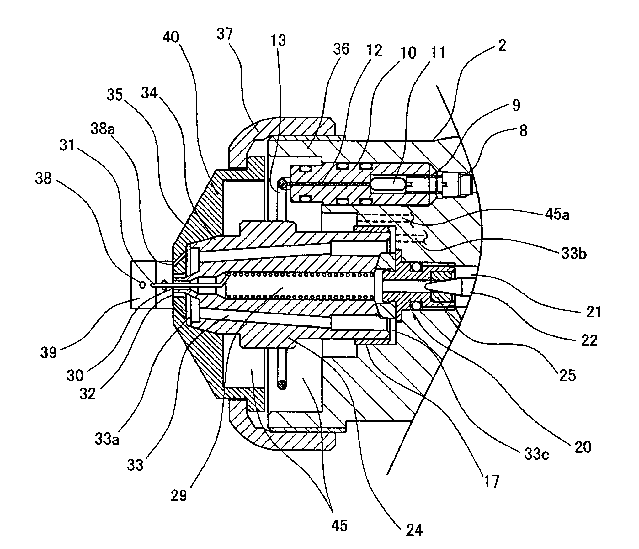
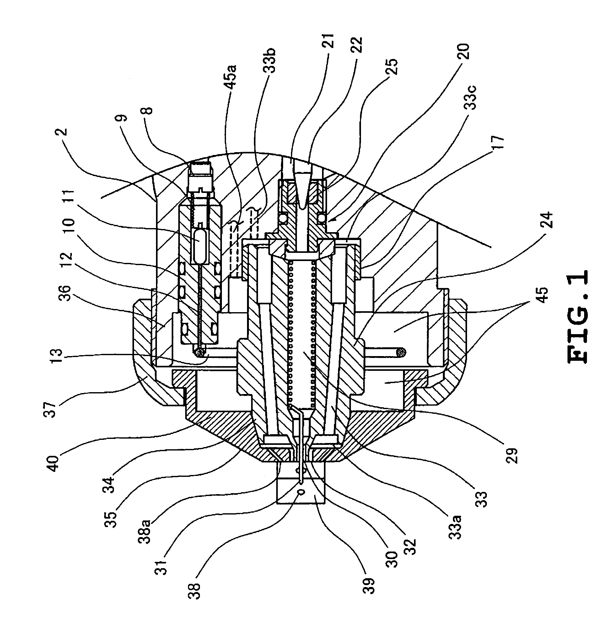
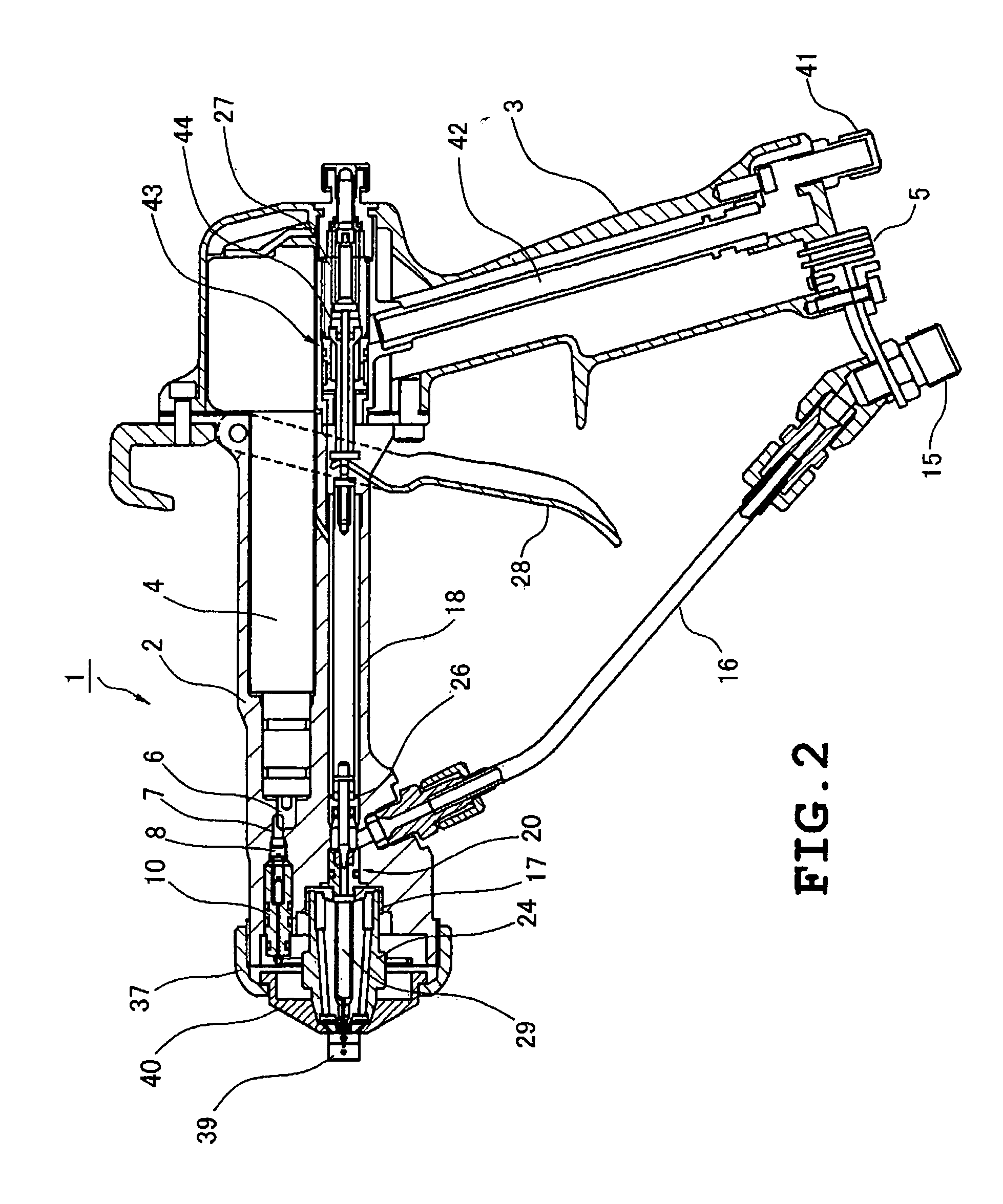
[0029]Hereinafter, a description is given of Embodiment 1 of an electrostatic coating spray gun (hereinafter called a “spray gun”) according to the invention with reference to FIG. 1 through FIG. 5. A spray gun according to the embodiment mainly uses, as a coating material, aqueous coating material or metallic coating material whose electric resistance is relatively low. FIG. 2 depicts a longitudinal sectional view of the entire structure of a spray gun 1 according to the embodiment. FIG. 1 depicts a longitudinal sectional view of the tip end region. FIG. 3 depicts a front elevational view of a tip end air cap 40 described later. FIG. 4 depicts a front elevational view of the tip end region of the spray gun 1 with its air cap 40 removed, and FIG. 5 depicts an example of a circuit that generates high voltage.

[0030]The spray gun 1 is composed of a barrel (gun tube) 2, which is the main body of a gun, and a grip 3 attached to the rear end region thereof as depicted in FIG. 2. The barre...

embodiment 2

[0053]The present embodiment is such that some improvements are added to Embodiment 1. In the case of Embodiment 1, since an intensive electric field directed from the pin electrode 31 to the electrode 13 exists, polarization is generated in the synthetic resin material that forms the air cap 40, and a polarized charge of the same polarity as that of the electrode 13 is produced on the surface of the air cap 40. In this connection, a part of the changed coating material particles, deviated from a forward conveyance air stream of the pattern air, of the atomized charged particles is caught by the polarized charge and may be adhered to the surface of the air cap 40. In the present embodiment, improvements are added, which prevents a coating material from being adhered to the surface of the air cap 40.

[0054]FIG. 6 is a longitudinal sectional view depicting the tip end region of the spray gun according to the present embodiment, FIG. 7 is a front elevational view depicting the tip end a...

embodiment 3

[0066]FIG. 11 is a longitudinal sectional view depicting the tip end region of the spray gun 1 according to the present embodiment. A point at which the present embodiment differs from Embodiment 2 resides only in that the pin electrode 31 is not provided. Generally speaking, an electric line of force is generated from a steepled part and a thin part, and the electric field intensity in the vicinity thereof is intensified. Based on this point, it is preferable that a thin pin electrode 31 is projected forward from inside the coating material delivery port 30. However, since the coating material itself has conductivity and is maintained at the grounding potential even if such a pin electrode 31 is not provided, the coating material can be atomized in an electrified state based on electrostatic induction. Also, an electric discharge occurs between the coating material at the outlet portion of the coating material delivery port 30 and the floating electrode 50 secured on the surface of...


PUM


Abstract

A spray gun suitable for electrostatic coating, using a coating material whose electric resistance is relatively low. A coating material nozzle is attached to the front middle region of a barrel having a forwardly projecting cylindrical section on the front outer peripheral edge, and an air cap which covers their front surfaces is installed. A pattern air flow channel is formed between the air cap, coating material nozzle outer peripheral surface and the cylindrical section inner peripheral surface, and an annular electrode is attached to the inside of the flow channel. The air cap is centrally provided with an atomization air spout hole, and a coating material delivery port at the front end of the coating material nozzle is inserted therein. A pin electrode is projected forward through the coating material delivery port. Two pairs of projections project forward from two sets of opposed locations for the air cap, each with a pattern air spout hole. The pin electrode is grounded and a high dc voltage is applied to the annular electrode.

Description

TECHNICAL FIELD[0001]The present invention relates to an electrostatic coating spray gun, in particular, to a spray gun suitable for electrostatic coating, using an aqueous coating material or a metallic coating material whose electric resistance is relatively low.BACKGROUND ART[0002]Generally, in coating materials used for electrostatic coating of vehicle bodies, etc., there is a solvent-based coating material (oil-based coating material) whose electric resistance is relatively high, an aqueous coating material (water-based coating material) whose electric resistance is relatively low, and a metallic coating material in which metallic powder is dispersed in the above coating materials. Of these, where carrying out electrostatic coating using an aqueous coating material or a metallic coating material whose electric resistance is relatively low, a current is caused to flow to the ground via a coating material feeding channel and a coating material tank if high voltage is applied dire...

Claims


Application Information

Patent Timeline
Patent Type & Authority Patents(United States)
IPC IPC(8): B05B5/00B05B1/28B05B5/03B05B5/053
CPCB05B5/03B05B5/043B05B5/0533B05B7/0815B05B7/066
Inventor AMARI, MASAHIKOMURATA, MASAMISOGAWA, TAKUHO
Owner ASAHI SANAC KK
Why Eureka
Try Eureka