Side illumination lens and luminescent device using the same

a technology of luminescent devices and side illumination, which is applied in the direction of discharge tube luminescent screens, lighting and heating apparatus, instruments, etc., can solve the problems of difficult application of the luminescent device to the backlight, complicated process of fabricating the lens, and limited use of conventional light emitting diodes. , to achieve the effect of reducing defective rate and fabrication costs of the lens, high output of light, and superior heat dissipation

Active Publication Date: 2010-07-06
SINOTECHNIX LLC
View PDF107 Cites 37 Cited by
  • Summary
  • Abstract
  • Description
  • Claims
  • Application Information

AI Technical Summary

Benefits of technology

[0018]As described above, according to the present invention, a lens with total internal reflection surfaces with different slopes, and a linear and / or curved refractive surface(s) allows light emitted forward from a luminescent chip to be guided to a side of the lens.
[0019]Further, a linear surface(s) formed in a direction perpendicular or parallel to a central axis of a lens and a curved surface are formed on an edge of the lens so that a process of fabricating the lens is facilitated, thereby reducing a defective rate and fabrication costs of the lens.
[0020]Moreover, it is possible to provide a luminescent device employing a heat sink to exhibit superior heat dissipation property, thereby obtaining high output of light.
[0021]Furthermore, after a heat sink is fixed to a frame, a package body can be formed using an insert molding technique, so that a luminescent device with a structure in which lead terminals and the heat sink are mutually coupled to each other can be easily fabricated.
[0022]In addition, it is possible to provide a frame that allows a heat sink to be fixed before a package body is formed, so that fabrication of a luminescent device is facilitated.
[0023]Further, there is an advantage in that a large quantity of luminescent devices can be mass-produced at a high rate because a method of fabricating the luminescent devices is similar to that of conventional top luminescent devices.

Problems solved by technology

Conventionally, colors of light emitted by a light emitting diode are only red and green, and thus, the conventional light emitting diode has its use limited to a display device.
Since the aforementioned luminescent device mainly emits light forward rather than sideward, there is a problem in that it is difficult to apply the luminescent device to a backlight which should widely emit light sideward.
Since the conventional lens has the plurality of refractive surfaces formed on right and left sides of the total reflection surface, there is a problem in that a process of fabricating the lens is complicated and fabricating costs increase.
That is, there are the following problems: if a lens is fabricated using a mold, upper and lower mold parts and right and left mold parts are required; and if a lens is fabricated by means of a casting or grinding method, it cannot be easily fabricated in view of its shape.

Method used


Image

  • Side illumination lens and luminescent device using the same
  • Side illumination lens and luminescent device using the same
  • Side illumination lens and luminescent device using the same

Examples


embodiment 1

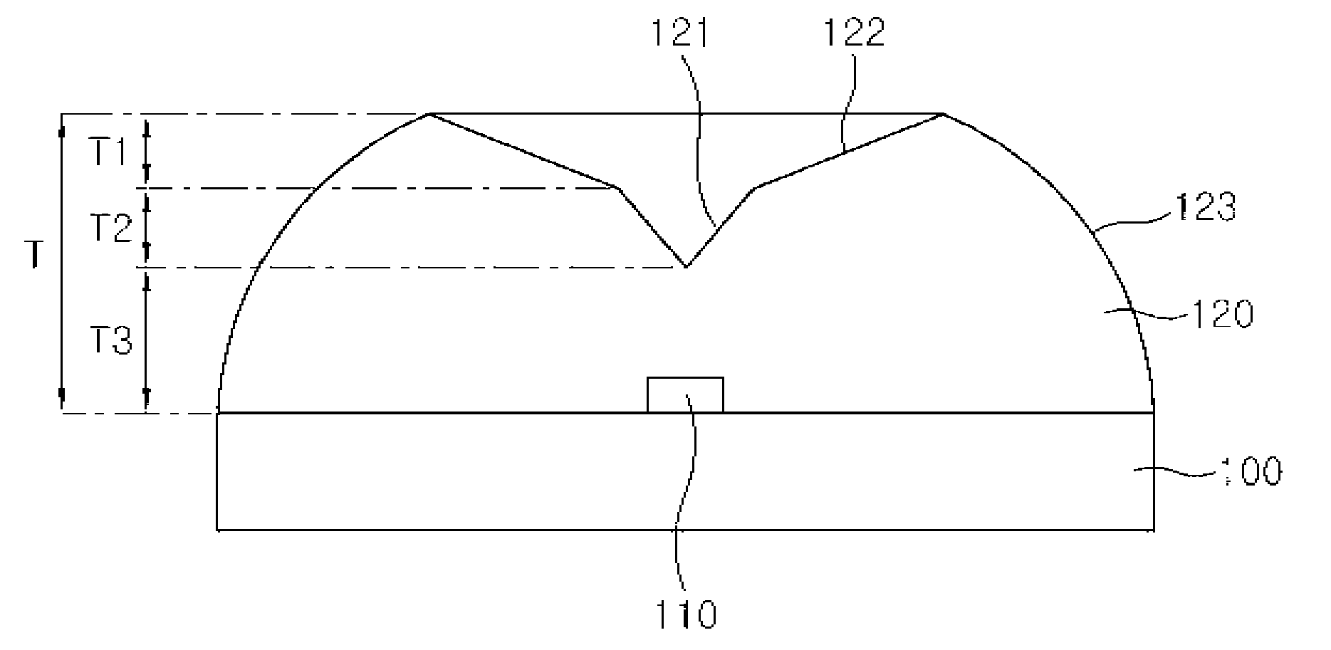
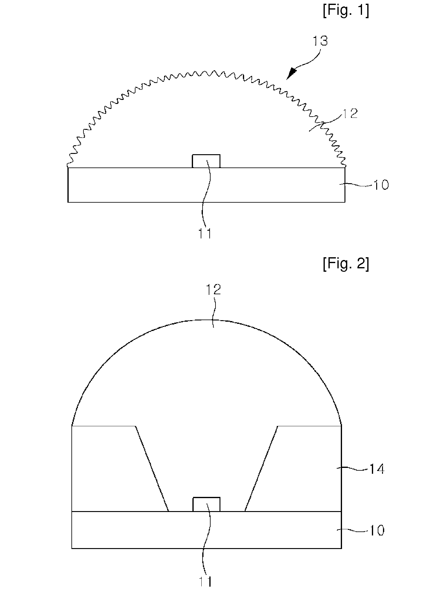
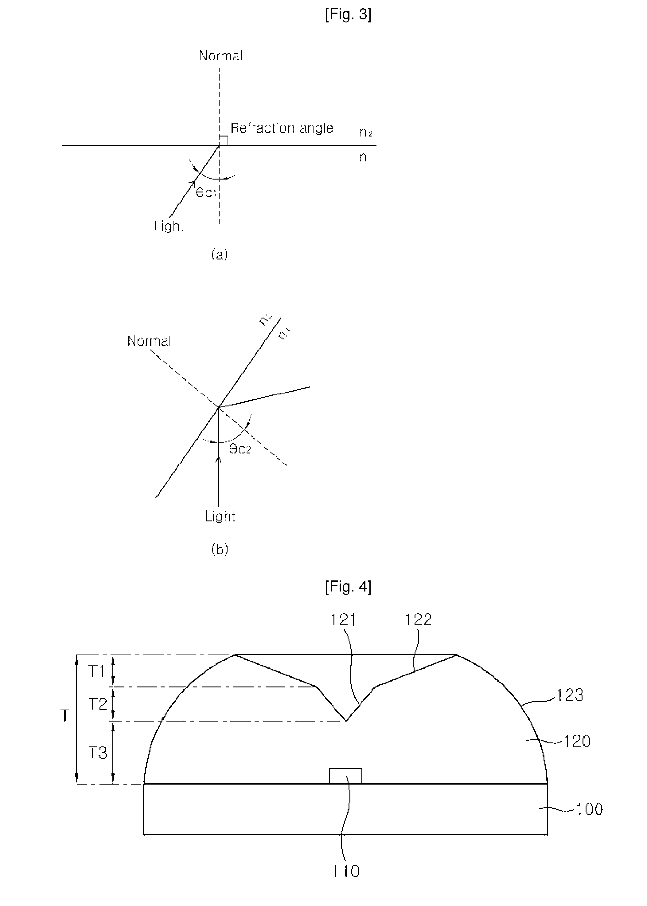
[0059]FIG. 4 is a sectional conceptual view of a luminescent device with a lens according to a first embodiment of the present invention, FIG. 5 is a plan view of the lens according to the first embodiment, FIG. 6 is a conceptual view illustrating the operation of the total internal reflection lens according to the first embodiment, FIG. 7 is a graph showing simulation results of the luminescent device with the lens according to the first embodiment, and FIGS. 8 and 9 are graphs showing experimental measurement results.

[0060]Referring to FIGS. 4, 5 and 6, the luminescent device with the lens according to this embodiment comprises a substrate 100; a luminescent chip 110 mounted on the substrate 100; and a lens that encapsulates the luminescent chip 110 and has a V-shaped first total reflection surface 121 with a predetermined slope with respect to a central axis, a second total reflection surface 122 extending outward therefrom with a slope smaller than that of the first total reflec...

embodiment 2

[0155]FIG. 29 is a conceptual sectional view of a luminescent device with a lens according to a second embodiment of the present invention, FIG. 30 is a perspective of the lens according to the second embodiment, FIG. 31 is a conceptual view illustrating the operation of the total internal reflection lens according to the second embodiment, and FIG. 32 is a graph showing simulation results of the luminescent device according to the second embodiment.

[0156]Referring to FIGS. 29, 30 and 31, the lens of this embodiment comprises a first total reflection surface 1121 with a V-shaped section and a certain slope with respect to a central axis x; a second total reflection surface 1122 with a slope smaller than that of the first total reflection surface 1121; a linear first refractive surface 1123a extending from a periphery of the second total reflection surface 1122 in a direction perpendicular to the central axis x; and a curved second refractive surface 1123b extending downward from a p...

embodiment 3

[0171]FIG. 33 is a conceptual sectional view of a luminescent device with a lens according to a third embodiment of the present invention, FIG. 34 is a perspective view of the lens according to the third embodiment, FIG. 35 is a conceptual view illustrating the operation of the total internal reflection lens according to the third embodiment, and FIG. 36 is a graph showing simulation results of the luminescent device according to the third embodiment.

[0172]Referring to FIGS. 33, 34 and 35, the lens of this embodiment comprises a first total reflection surface 2121 with a V-shaped section and a certain slope with respect to a central axis x; a second total reflection surface 2122 with a slope smaller than that of the first total reflection surface 2121; a curved first refractive surface 2123a extending downward from a periphery of the second total reflection surface 2122; a linear second refractive surface 2123b extending from a periphery of the first refractive surface 2123a in a di...


PUM


Abstract

The present invention relates to a side illumination lens and a luminescent device using the same, and provides a body, a total reflection surface with a total reflection slope with respect to a central axis of the body, and a linear and / or curved refractive surface(s) formed to extend from a periphery of the total reflection surface; and a luminescent device including the lens. According to the present invention, a lens with total internal reflection surfaces with different slopes, and a linear and / or curved refractive surface(s) allows light emitted forward from a luminescent chip to be guided to a side of the lens. Further, a linear surface(s) formed in a direction perpendicular or parallel to a central axis of a lens and a curved surface are formed on an edge of the lens so that a process of fabricating the lens is facilitated, thereby reducing a defective rate and fabrication costs of the lens.

Description

TECHNICAL FIELD[0001]The present invention relates to a side illumination lens and a luminescent device using the same, and more particularly, to a side illumination lens utilizing total internal reflection and a luminescent device using the lens.BACKGROUND ART[0002]In general, a light emitting diode (LED) is a device utilizing a phenomenon in which minority carriers (electrons or holes) injected by means of a p-n junction structure of a semiconductor are produced, and light is emitted due to recombination of the carriers. Conventionally, colors of light emitted by a light emitting diode are only red and green, and thus, the conventional light emitting diode has its use limited to a display device.[0003]With the development of technology, however, light emission is allowed in various ranges of wavelength, in addition to blue light emission. Thus, a light emitting diode has begun to be used in a variety of fields. In particular, as white light emission is realized, the use of the lig...

Claims


Application Information

Patent Timeline
Patent Type & Authority Patents(United States)
IPC IPC(8): F21V5/00H01L33/54
CPCH01L33/54G02B19/0071G02B19/0028G02B19/0061H01L2924/19107H01L2224/48247H01L2224/48091H01L2924/00014
Inventor KIM, DO-HYUNGLEE, CHUNG-HOONLEE, KEON-YOUNGPARK, KWANG-IL
Owner SINOTECHNIX LLC
Why Eureka
Try Eureka