Optical information detecting method, optical head, and optical disc apparatus utilizing plural photodetectors
a technology of optical discs and optical head, applied in the field of optical head, optical disc apparatus utilizing plural photodetectors, can solve the problems of difficult application of disclosed techniques for practical purposes, unsuitable for reducing the size of optical systems, etc., and achieves small reflected signals, low reflectivity, and increase the s/n ratio
- Summary
- Abstract
- Description
- Claims
- Application Information
AI Technical Summary
Benefits of technology
Problems solved by technology
Method used
Image
Examples
embodiment 1
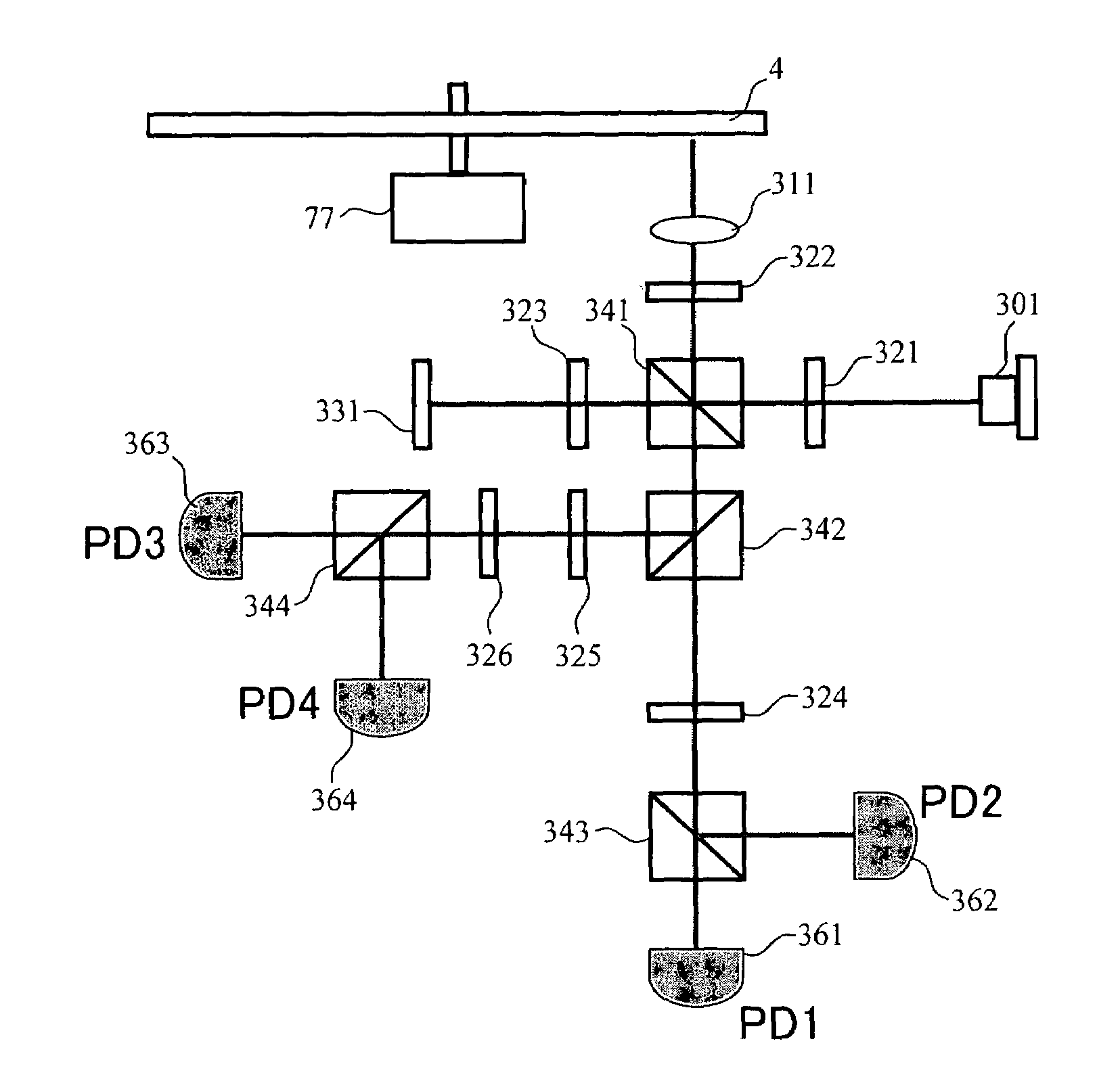
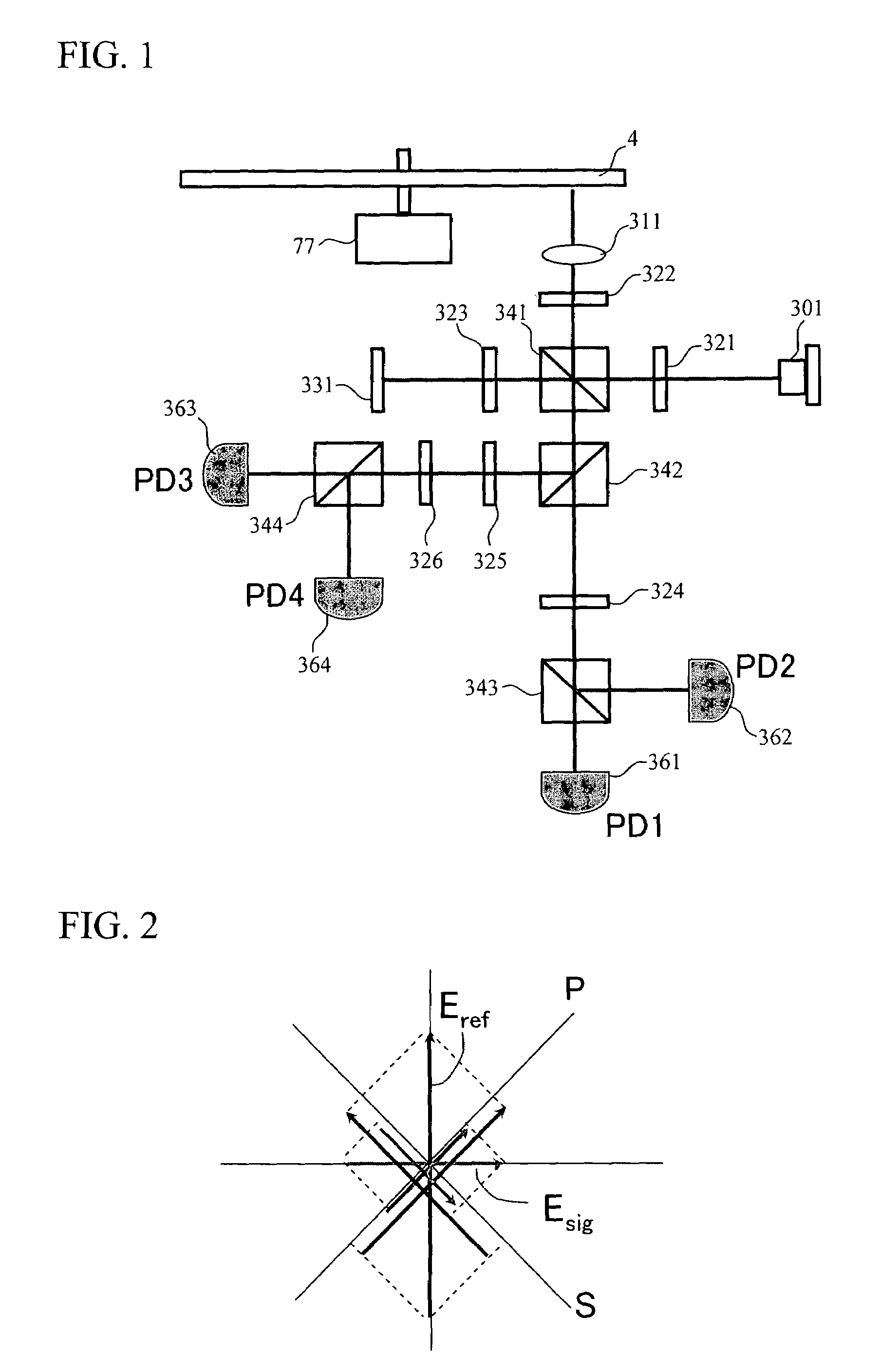
[0053]FIG. 1 shows a block diagram of an optical system for realizing an optical signal detecting method of the present invention. Light emitted by a laser 301 passes through a first λ / 2 plate 321 whereby the polarization direction of the light is rotated by 45°. The light with the rotated polarization is separated by a first polarizing beam splitter 341 into two beams of linearly polarized light that are perpendicular to each other. The light with one polarization (detection light) is reflected and passes through a first λ / 4 plate 322, by which the light is converted into circularly polarized light, which is focused by an objective lens 311 and shone onto an optical disc 4. Reflected light (to be hereafter referred to as a signal light) from the optical disc 4 as it is rotated by a spindle motor 77, is returned back to parallel light by the objective lens 311 and then back to linearly polarized light via the first λ / 4 plate 322. The direction of this linearly polarized light is per...
embodiment 2
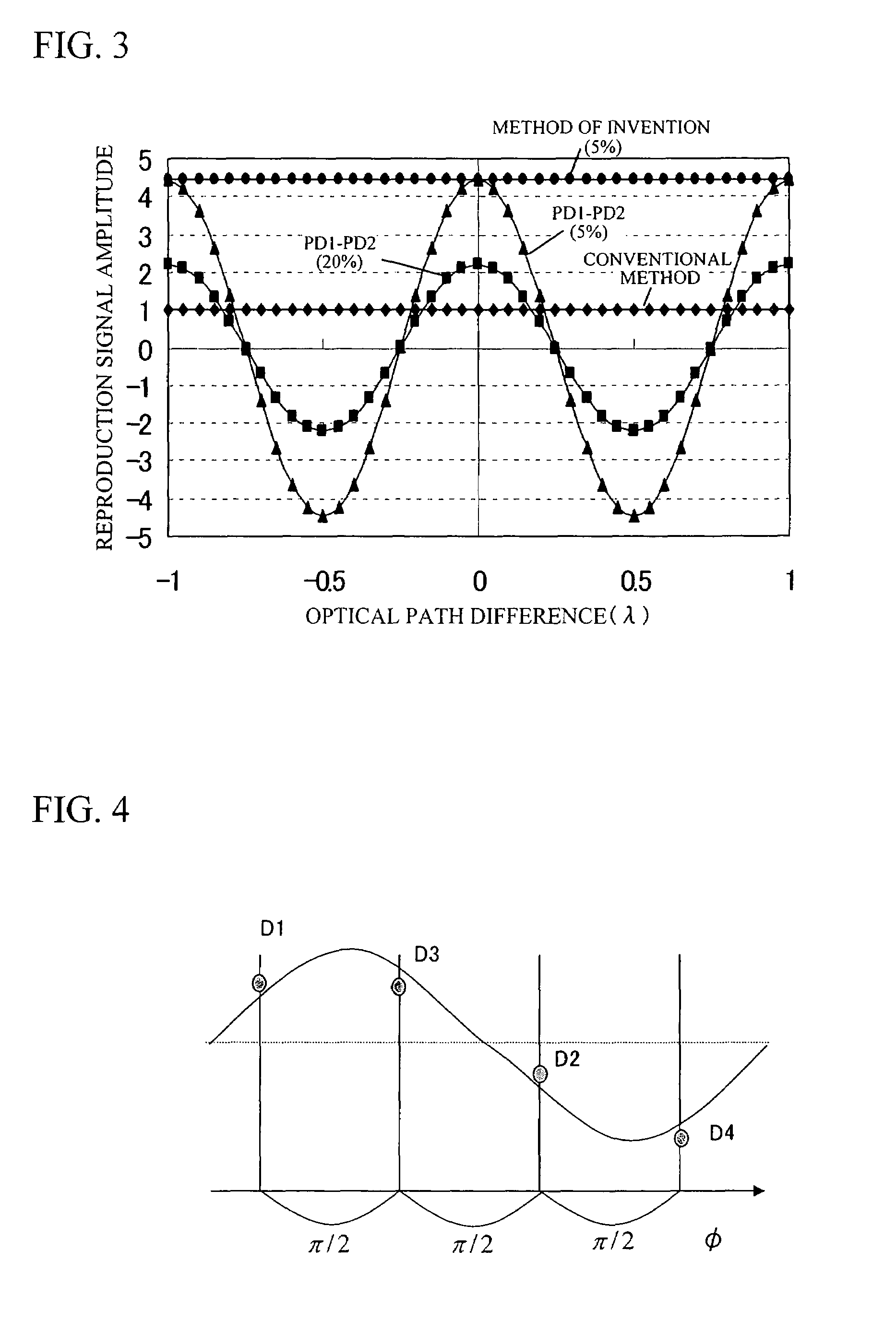
[0065]While in Embodiment 1 signal light and reference light were assumed to be completely coherent, the resonator length of conventional semiconductor lasers is short and their optical coherence length is not very long. FIGS. 8A to 8C show the change in reproduction signal intensity in a case where, in the configuration of Embodiment 1, a conventional blue-light semiconductor laser (LD) was employed. In order to track the disc as it undulates, the objective lens 311 is moved up and down, resulting in changes in the optical path length of the signal light. However, since the optical path length of reference light does not change, an optical path length difference is created between reference light and signal light. If such optical path length difference becomes greater than the coherence length of LD, the output of Equation (7) cannot be obtained. Generally, the output in an incompletely coherent state is Equation (7) times coherency. Coherency is 1, i.e., 100%, in a completely cohe...
embodiment 3
[0068]While in Embodiments 1 and 2 a reproduction signal was obtained by the operation according to Equation (7), it is also possible to obtain a reproduction signal without performing the square-root operation.
[0069]Namely, (Sig1)2+(Sig2)2=|Esig|2·|Eref|2 is used as the signal. Such operation does not require the square-root operation, so that the circuit configuration can be simplified and the energy of signal light becomes proportional to reproduction output. Since the reproduction signal output is also proportional to |Esig|2 in the conventional optical signal detection method, the method of the present embodiment has the advantage that it can employ the same conventional signal processing method.
PUM
 Abstract
Description
Claims
Application Information
 - R&D
- Intellectual Property
- Life Sciences
- Materials
- Tech Scout
- Unparalleled Data Quality
- Higher Quality Content
- 60% Fewer Hallucinations
Browse by: Latest US Patents, China's latest patents, Technical Efficacy Thesaurus, Application Domain, Technology Topic, Popular Technical Reports.
© 2025 PatSnap. All rights reserved.Legal|Privacy policy|Modern Slavery Act Transparency Statement|Sitemap|About US| Contact US: help@patsnap.com


