
Self-tuning active engine mount for vehicles with active fuel management engine

a technology of fuel management engine and active engine, which is applied in the direction of shock absorber, jet propulsion mounting, instruments, etc., can solve the problems of n&v, performance, noise and vibration, increased structural vibration,

Inactive Publication Date: 2010-07-06
GM GLOBAL TECH OPERATIONS LLC
View PDF17 Cites 22 Cited by
  • Summary
  • Abstract
  • Description
  • Claims
  • Application Information

AI Technical Summary

Benefits of technology

The present invention provides an improved method for counteracting forces transmitted from an engine to a vehicle frame using a force-generating apparatus. The method involves actively generating a pressure pulse that is a function of the engine's rotational speed and selectively communicating it to the engine mount assembly. The driving member integrated into the engine mount assembly applies a counteracting force to the frame in response to the resultant forces transmitted to the frame. The force-generating apparatus includes a circuit operatively connected to the engine mount assembly and a hydraulic circuit in fluid communication with the engine mount assembly. The hydraulic circuit includes a pump or a high pressure pump and an on / off valve that selectively pressurizes the driving member. The present invention provides an automatic and simple control system for active engine mounts without the need for additional sensors.

Problems solved by technology

This higher firing force, in turn, causes torque variations, which produce increased structural vibrations, thereby degrading noise and vibration, N&V, performance.
These systems usually provide less acceptable damping at other frequencies.
Therefore, conventional passive approaches of vibration suppression may not meet the N&V requirement for both AFM mode and normal mode of engine operation.
Furthermore, conventional hydraulic-based mounts can be very cumbersome and expensive, as integrated sensors and control hardware must be configured to monitor and respond to the specific frequency of the transmitted force.
Such independent mechanisms often require expensive and complex control units to effectively cancel engine induced forces.

Method used


Image

  • Self-tuning active engine mount for vehicles with active fuel management engine
  • Self-tuning active engine mount for vehicles with active fuel management engine
  • Self-tuning active engine mount for vehicles with active fuel management engine

Examples


second embodiment

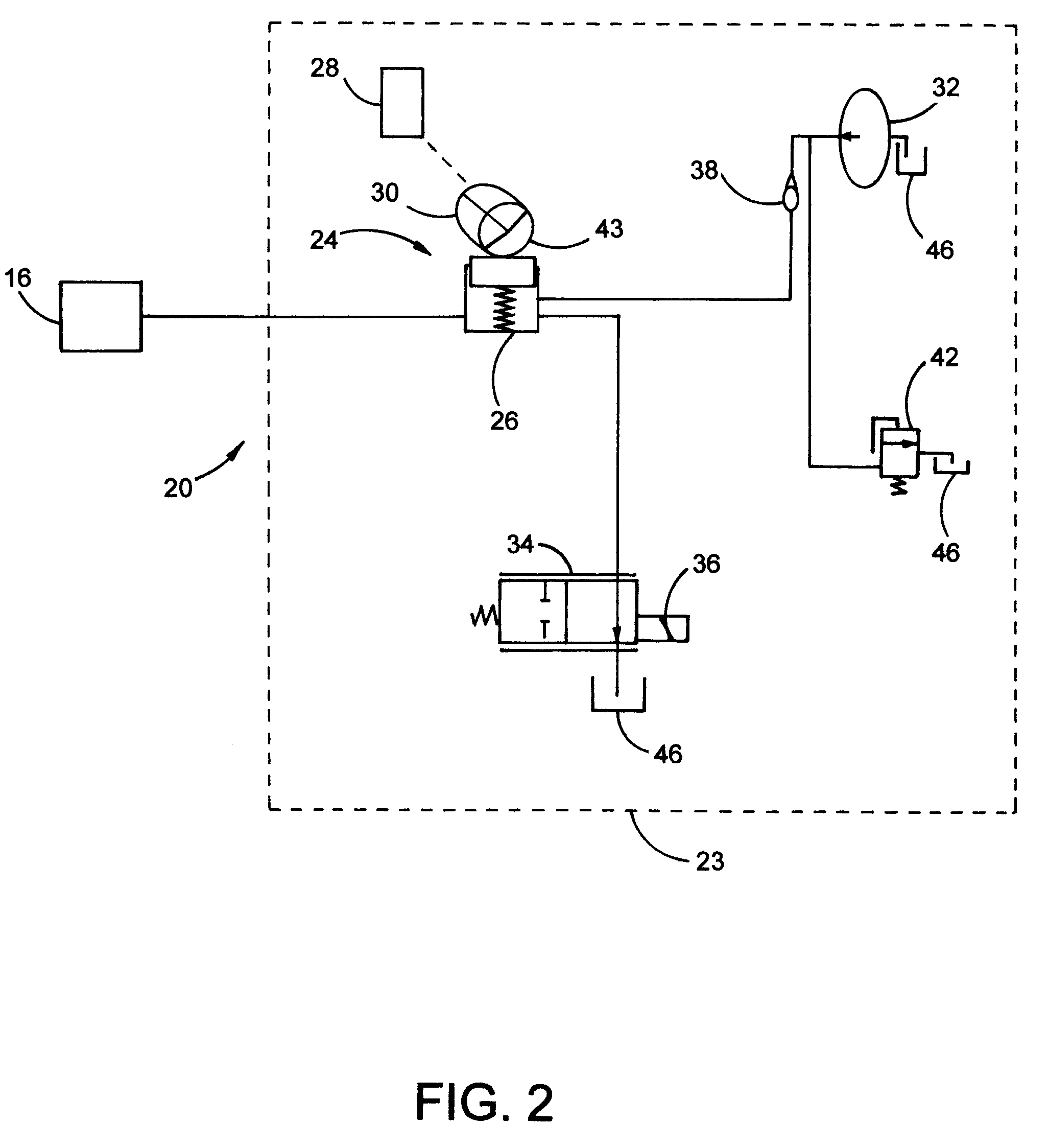
[0030]Referring now to FIG. 3, a hydraulic circuit 21 in accordance to the present invention is shown. The hydraulic circuit 21 comprises a solenoid valve 44 operatively connected to the crankshaft 28, such that the solenoid valve 44 is energized via current timing of which is synchronized with rotation of the crankshaft 28. The solenoid valve 44 can be a two-position on / off valve, or any suitable valve known in the art. In addition, the solenoid valve 44 is energized with an on-time frequency that is directly tied to the rotational speed of the crankshaft 28. For example, the frequency of the solenoid valve 44 can be tuned to the crank frequency by utilizing existing spark-timing control methods, or any other suitable method known in the art. Moreover, the solenoid valve 44 receives high pressure hydraulic fluid from a powered fluid source, and is configured to control the supply of pressurized hydraulic fluid to the ram 22. Thus, when the solenoid valve 44 is energized, it operate...

first embodiment

[0032]The hydraulic circuit 21 further comprises a proportional valve 34 fluidly connected to the high pressure pump 40 and the solenoid valve 44. The proportional valve 34 includes a spool (not shown) for movement therein. The proportional valve 34 is operatively connected to a control module 36 and operable to regulate pressure within the hydraulic circuit 21, wherein the proportional valve 34 is responsive to control signals submitted from the control module 36. Moreover, the proportional valve 34 is configured to bleed out the hydraulic circuit 21 in order to control the amplitude of the pressure pulses. As in the first embodiment, the proportional valve 34 is modulated in accordance to engine speed, not per engine cycle (i.e., crank rotation), and is configured to yield a certain phasing corresponding to a certain amplitude. That is, the proportional valve 34 is only controlled if there is a change in engine speed, and otherwise remains steady without control so long as engine ...


PUM


Abstract

An active engine mount assembly for counteracting resultant forces in active fuel management systems, wherein resultant forces are transmitted to a frame of a motorized vehicle generated by the deactivation of at least one cylinder in an internal combustion engine. The active engine mount assembly is fluidly connected to a hydraulic circuit. The hydraulic circuit is operatively connected to an engine crankshaft and operable to actively generate pressure pulses having frequencies self-synchronized with the rotational speed of the crankshaft.

Description

TECHNICAL FIELD[0001]The present invention relates generally to engine mounting systems, and more specifically, to an apparatus and method for counteracting oscillatory forces transmitted to a body of a vehicle equipped with an active fuel management engine.BACKGROUND OF THE INVENTION[0002]In recent years, many manufacturers have developed Active Fuel Management (AFM), formerly called Displacement on Demand, systems to improve the fuel economy of internal combustion engines. An AFM engine operates in a normal mode (all cylinders are active) when power above a predetermined threshold is required and in an AFM mode (at least one cylinder is deactivated) when power requirement is reduced. AFM mode produces a higher level of firing force, as a result of increased in-cylinder pressures, for each active cylinder. This higher firing force, in turn, causes torque variations, which produce increased structural vibrations, thereby degrading noise and vibration, N&V, performance. In addition, ...

Claims


Application Information

Patent Timeline
Patent Type & Authority Patents(United States)
IPC IPC(8): G06F19/00F16F13/04F02D17/02F16F15/20
CPCF16F15/027
Inventor GECIM, BURAK A.MAGUIRE, JOEL M.BUCKNOR, NORMAN K.
Owner GM GLOBAL TECH OPERATIONS LLC
Learn More