Engine

a technology of engine and gas tank, applied in the field of engines, can solve the problems of inability to increase a load to more than a half load of conventional engines, loud combustion noise, and large amount of fuel supply, and achieve the effects of reducing the amount of required egr gas, slowing down, and low load

Inactive Publication Date: 2010-07-13
HATAMURA KOICHI
View PDF15 Cites 26 Cited by
  • Summary
  • Abstract
  • Description
  • Claims
  • Application Information

AI Technical Summary

Benefits of technology

[0026]According to the invention, it is structured that the EGR gas is introduced into the cylinder at the part of the power stroke, for example, from the end stage of the power stroke to the early stage of the exhaust stroke, preferably, using the pressure in the combustion chamber just before the exhaust valve is opened, and at least, in the early stage of the compression stroke, so that the EGR gas is introduced into the cylinder using the pressure in the high-pressure combustion chamber to thereby cause the pressure in the combustion chamber at the start of the compression stroke to increase to higher than the intake port pressure. Specifically, the supercharge effect can be obtained. Further, the compression pressure is increased together, in which the compression temperature required for the HCCI combustion downs, so that the required EGR gas amount is reduced as compared with the engine without supercharge effect.
[0027]According to the invention, it is structured that the intake air is breathed by opening the intake valve to the bottom dead center of the intake stroke and, at the same time, that the EGR gas is introduced into the cylinder using the pressure of the combustion chamber in the part of the power stroke, accordingly the intake air is introduced from the intake valve as usual and thereby the introduction amount of the EGR gas can be increased without reducing the amount of the intake air and the pressure in the combustion chamber can be increased to higher than that of the intake port, so that the supercharge effect can be obtained. Note that there is a case where an external chilled EGR gas is introduced to slow down a burning velocity, and in that case, after the mixture of the fresh air and the external EGR gas is introduced from the intake valve as usual, the same effect can be obtained, of course.
[0028]Here, in the present invention, the EGR gas is introduced in the early stage or the first-half of the compression stroke, however, the introduction of the EGR gas may start in the end stage of the intake stroke. When doing so, even when taking time to fully open the valve for introducing the EGR gas, the EGR gas amount can be ensured. The operation zone introducing the EGR gas has a relatively low load, hence, even when the intake air amount is slightly reduced by starting introducing the EGR gas in the intake stroke, that causes no trouble.
[0029]According to the invention, it is structured that the pressure wave by the blowdown gas of the first cylinder is introduced into the second cylinder in the early stage of the compression stroke of the second cylinder, and thereby the bulk of EGR gas can be introduced into the second cylinder using the pressure wave of the first cylinder, so that the above-described supercharge effect can be realized with a simple structure.
[0030]More specifically, the pressure wave by the blowdown gas by the pressure of the combustion chamber in the end stage of the power stroke of the first cylinder, preferably, just before the exhaust valve thereof is opened is introduced into the second cylinder at least in the early stage of the compression stroke of the second cylinder, preferably, just after the intake valve thereof is closed. In this case, the fresh air is introduced from the intake valve as usual, in which therefore almost the same fresh air mass as of the conventional engine is introduced, so that the EGR gas is introduced into the cylinder by the pressure wave of the high-pressure blowdown gas after the intake valve closes. Accordingly, the fresh air is not pushed out by the EGR gas, and thereby the air-fuel mixture mass increases to the extent thereof, so that the pressure in the combustion chamber at the start of the compression is increased to higher than the intake port pressure. Further, in the case of the HCCI engine, with the high-temperature blowdown gas, the high compression temperature needed for the HCCI combustion can be ensured easily and surely.
[0031]According to the invention, the exhaust timing of the first cylinder and the length of the exhaust pipe from the first cylinder to the second cylinder are set so that the pressure wave by the blowdown gas of the first cylinder is introduced into the exhaust port of the second cylinder in the early stage or in the first half of the compression stroke of the second cylinder, preferably, just after the intake valve thereof is closed, and in addition, the exhaust valve of the second cylinder is opened at least in the early stage of the compression stroke of the second cylinder, so that the air-fuel mixture mass of the second cylinder can be increased using the pressure wave by the blowdown gas of the first cylinder.

Problems solved by technology

Specifically, when the air-fuel mixture mass does not increase, the fuel supply amount is limited to increase, and as a result, it is impossible to increase a load to more than a half load of conventional engines (G / F=15).
Further, when a fuel injection amount is increased under the condition of a constant air-fuel mixture mass, a loud combustion noise arises caused by a pressure increase ratio due to a rapid temperature increase.
This is also the cause not allowing the load increase by constraining G / F.
As a result, in a naturally aspirated (NA) engine limited to increase the air-fuel mixture mass, the higher limit of a high-efficient and super-low NOx HCCI operation zone is limited to about a half load of the conventional engines.

Method used


Image

  • Engine
  • Engine
  • Engine

Examples


Embodiment Construction

[0073]Hereinafter, modes according to the present invention will be described based on the attached drawings.

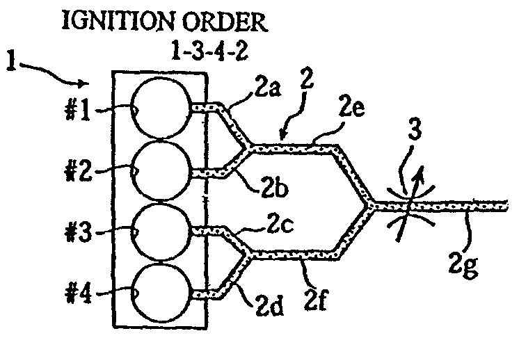
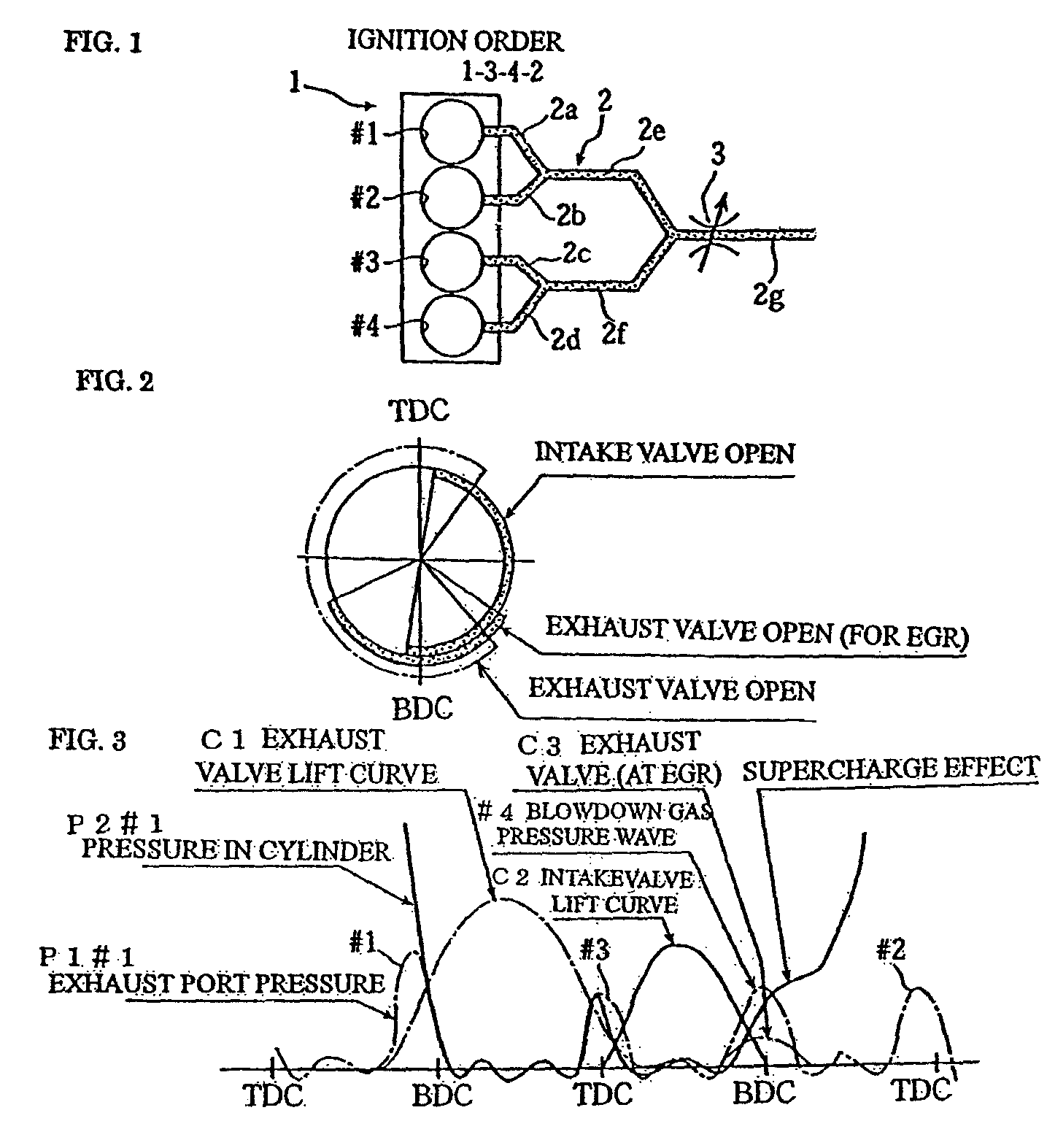
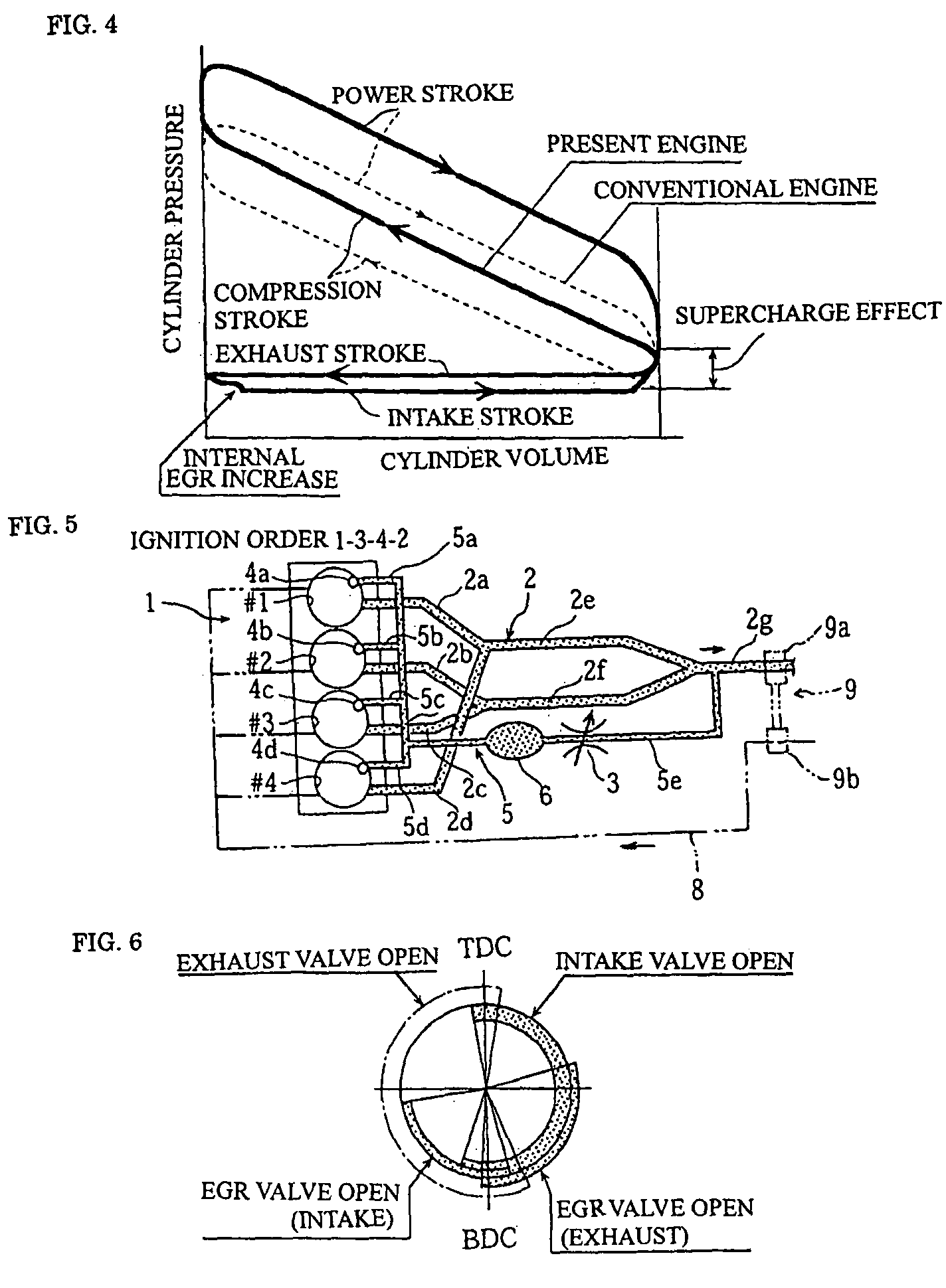
[0074]FIGS. 1 to 4 are views to illustrate an engine supercharging a blowdown pressure wave according to a first mode of the present invention, in which FIG. 1 is an overall block diagram, FIG. 2 is a valve timing diagram, FIG. 2 is a characteristic view showing a valve timing, a blowdown gas pressure and a pressure in a cylinder, and FIG. 4 is a view showing a pressure-volume relation.

[0075]In the drawings, “1” denotes a four-cylinder HCCI engine including a first cylinder #1 to a fourth cylinder #4 to be ignited in the order of the cylinders #1-#3-#4-#2. Accordingly, in view of the ignition timing, the first cylinder #1 and the fourth cylinder #4, and the second cylinder #2 and the third cylinder #3 have a phase difference of 360 degrees in terms of a crank angle, respectively.

[0076]“2” denotes an exhaust device including first to fourth exhaust branch pipes 2a to 2d connec...


PUM


Abstract

The present invention provides an engine capable of increasing an introducing amount of an EGR gas without reducing an introducing amount of a fresh air. In an engine structured to introduce fresh air and an EGR gas into a cylinder, the EGR gas is introduced into the cylinder at least at a part of a compression stroke using a pressure in a combustion chamber at least at a part of a power stroke.

Description

TECHNICAL FIELD[0001]The present invention relates an engine structured to introduce a fresh air and an EGR gas into a cylinder and, more particularly to, an improvement on an EGR-gas introduction method allowing the introduction amount of the EGR gas to increase while the introduction amount of the fresh air is prevented from reducing with a simple structure. The present invention is suitable for a Homogeneous Charge Compression Ignition (HCCI) engine, and therefore, hereinafter, the description will be given by taking the HCCI engine for main instance.BACKGROUND ART[0002]The Homogeneous Charge Compression Ignition engine is an engine of a system in which fuel is injected into a combustion chamber earlier or the fuel and a gas are mixed in an intake port and the premixed air-fuel mixture is caused to self-ignite in the vicinity of a compression dead center backed by a combustion reaction caused by a compression temperature, while a general diesel engine feeds by injecting the fuel ...

Claims


Application Information

Patent Timeline
Patent Type & Authority Patents(United States)
IPC IPC(8): F02B47/08F02B47/10
CPCF01N13/107F02D13/0265F02D13/0276F02D21/08F01N13/011F02M25/0748F02M25/0752F01N13/009F02M25/0743F01N2260/14F01N2430/10Y02T10/121Y02T10/18F02M26/01F02M26/37F02M26/42Y02T10/12
Inventor HATAMURA, KOICHI
Owner HATAMURA KOICHI
Why Eureka
Try Eureka