Exercise apparatus based on a variable mode hydraulic cylinder and method for same

a hydraulic cylinder and variable-mode technology, applied in the direction of sport apparatus, muscle exercise devices, gymnastic exercise, etc., can solve the problem of not being able to safely achieve prior art applications, and achieve the effect of safe challenge to professional level athletes, high acceleration/speed, and minimizing the distance between valves and cylinder ends

Active Publication Date: 2010-07-27
FOI GRP
View PDF28 Cites 25 Cited by
  • Summary
  • Abstract
  • Description
  • Claims
  • Application Information

AI Technical Summary

Benefits of technology

[0009]The ends of the rodless hydraulic cylinder are sealed by a water control spool valve and a controllable pressure relief valve. The water control spool valves adjustably permits water to enter and exit the hydraulic cylinder to regulate the direction and speed of movement of the piston. The controllable pressure relief valve controls maximum pressure at each end regardless of whether the flow controlling spool valve is admitting water to a cylinder end. Thus, the internal speed, direction and force of movement of the piston can be controlled.
[0010]In order to produce accelerations and velocity sufficient to safely challenge professional level athletes the invention minimizes the distance between valves and cylinder end, utilizes large valves and ports and the non-positive sealing piston. Additionally, the water supply side of the valve is a hybrid of a closed loop and open loop system. Water is flowing at high speed thru the length of the extended center section of the spool valve at a regulated system pressure. Thus, when the spool valve opens the admitted water is at full velocity and pressure. The flowing nature of the center section additionally prevents water hammer as the water always has a travel path. The invention can deliver high acceleration / speed, high force resistance; high acceleration / speed, low force resistance; low acceleration / speed, high force resistance; or low acceleration / speed, low force resistance exercise forces and movements depending on the water flow, internal pressure, and resulting generated forces.

Problems solved by technology

The device's goal is to enable quick response strength training that can not safely be accomplished with prior art applications whether by harnessing hydraulic forces or using other methods.

Method used


Image

  • Exercise apparatus based on a variable mode hydraulic cylinder and method for same
  • Exercise apparatus based on a variable mode hydraulic cylinder and method for same
  • Exercise apparatus based on a variable mode hydraulic cylinder and method for same

Examples


first embodiment

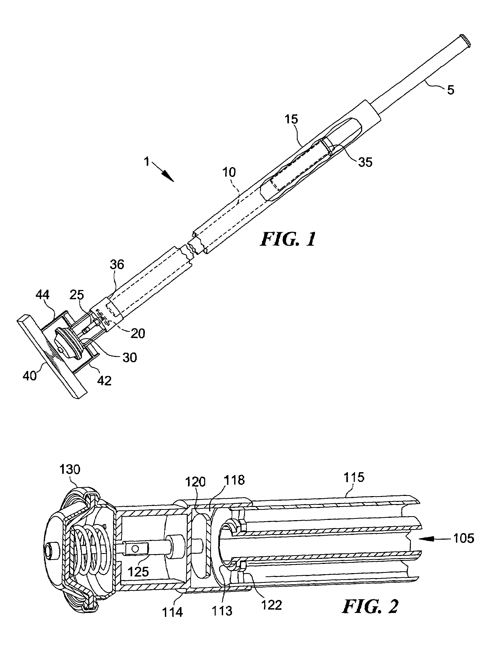
[0019]For the first embodiment, referring to FIG. 1, the components of the variable mode hydraulic cylinder 1 basically include three cylindrical tubes mated in a concentric manner. A water flow tube 5 connected to a pump or pressurized water source slides into a second tube or hydraulic cylinder 10. The water flow tube 5 possesses a smaller diameter and the mating of the water flow tube 5 and hydraulic cylinder 10 provides a tight fit to restrict or prevent water from flowing back over the exterior of the water flow tube 5, but this fit does not form a water tight seal that can resist all the pressure that can be generated within the hydraulic cylinder 10. Rather, the fit is tight enough to restrict and generally prevent water from flowing out, but the fit is loose enough so that there is little friction between the hydraulic cylinder 10 and the water flow tube 5 allowing the hydraulic cylinder 10 to slide freely over the water flow tube 5. The hydraulic cylinder 10 slides back and...

second embodiment

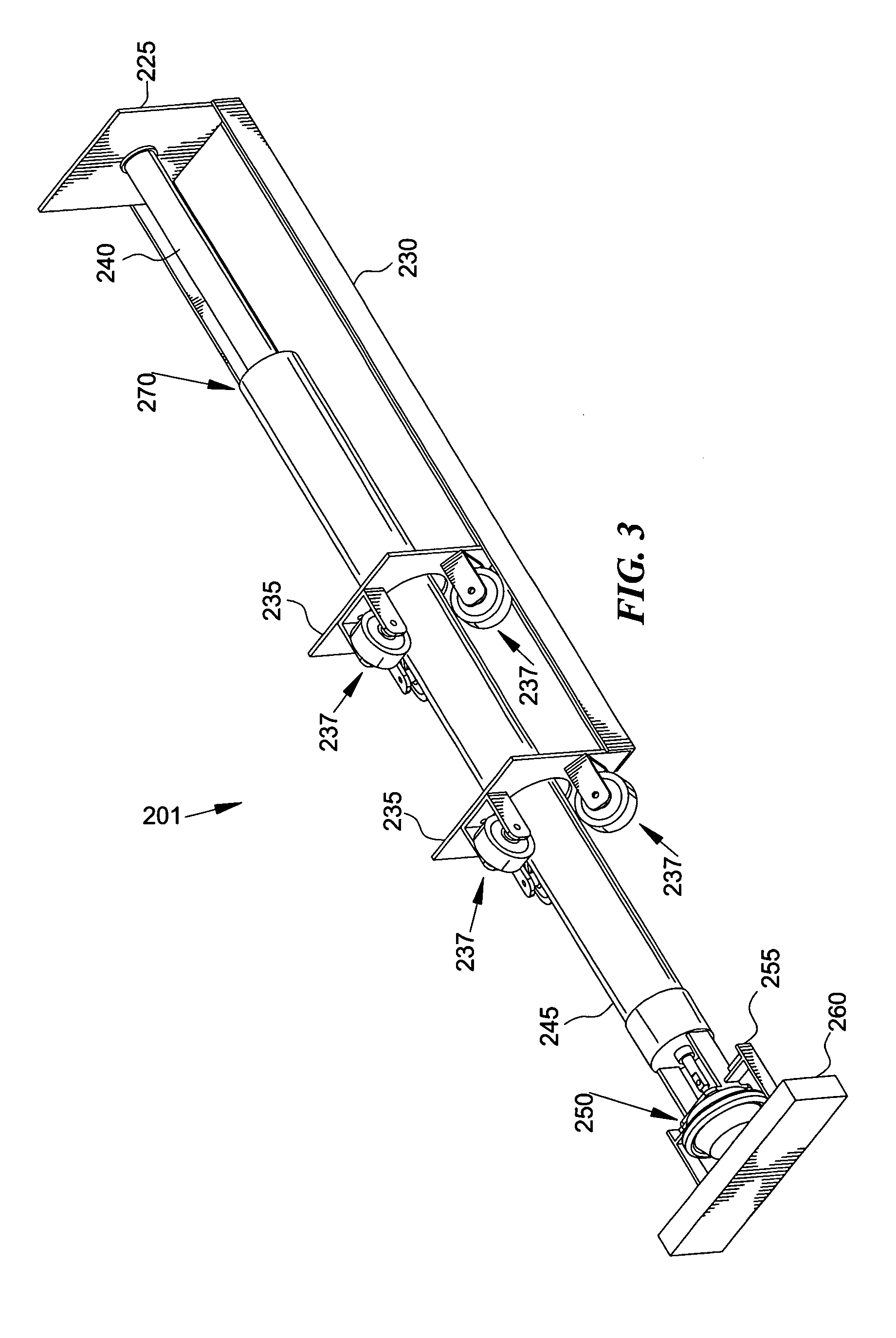
[0034]FIG. 5 shows a second embodiment, which is the preferred embodiment, for a hydraulic cylinder generating a fast responding controllable force. The hydraulic cylinder in this embodiment includes a hydraulic cylinder 405 with an internal piston moving bi-directionally. The piston inside the hydraulic cylinder 405 bi-directionally operates a cable and pulley system 410. This type of hydraulic cylinder is also referred to as a rodless cylinder. Water flows into either end of the hydraulic cylinder 405 through an elongated spool valve 415. A spool actuator 420 controls the water flow into the hydraulic cylinder 405 which flows out through a pair of spool exhaust ports 425. A pair of air controlled full-flow adjustable relief valves 430 regulate the pressure of the water flow within the respective sides of the cylinder and thus the force generated on the piston in the hydraulic cylinder 405 independent of spool valve position. The spool valve 435 provides a path for water entering t...


PUM


Abstract

The invention is a hydraulic cylinder for use in exercise machines to deliver a controllable fast acting force. The invention uses a hydraulic cylinder with features that allow high acceleration rates, rapid changes of force level and direction, and positive force limitation. In the preferred embodiment, the hydraulic cylinder is composed of a rodless, hydraulic cylinder coupled to a cable and pulley system. A water source delivers water to generate a force against an inner bi-directionally moving piston to generate a regulated movement and force.
The ends of the rodless hydraulic cylinder are sealed by both a water control spool valve and a controllable poppet style pressure relief valve. The water control spool valves adjustably permits water to enter and exit the hydraulic cylinder to regulate the direction and speed of movement of the piston. The pressure relief valve controls the desired maximum pressure and corresponding forces exerted on cylinder. Thus, both the internal speed and force of movement of the piston can be controlled. The invention can deliver high acceleration/speed, high force resistance; high acceleration/speed, low force resistance; low acceleration/speed, high force resistance; or low acceleration/speed, low force resistance exercise forces and movements depending on the water flow, internal pressure, and resulting generated forces.

Description

BACKGROUND OF THE INVENTION[0001]Exercise machines and apparatus using hydraulic cylinders as a resistance or power source have existed for some time. Generally, these prior art methods are limited by design and physics in terms of restricted direction of resistance and speed of response.[0002]The exercise modality for most exercising equipment harnessing hydraulic force is aimed at building strength, muscle mass, and muscle tone. For example, hydraulic dampers have been used to generate a resistance force. This force is generally passive and only provides either a fixed or variable resistance force. An example of such a passive exercise machine is found in U.S. Pat. No. 5,527,251 to Davis which provides for a bidirectional, adjustable resistance exercise machine. Another exercise application for a hydraulic cylinder is found in U.S. Pat. No. 5,803,879 to Huang for a double-acting hydraulic cylinder that delivers a variable resistance to provide a smooth movement and resistance in t...

Claims


Application Information

Patent Timeline
Patent Type & Authority Patents(United States)
IPC IPC(8): A63B21/008
CPCA63B21/00069A63B21/0083A63B21/154A63B69/345A63B21/1488A63B21/00072A63B21/4045A63B69/34
Inventor MUNSON, JR., DAVID MURRAYFLATT, DAVID SHAWN
Owner FOI GRP
Why Eureka
Try Eureka