Integral suction device with acoustic panel

a technology of air inlet control and suction device, which is applied in the direction of machines/engines, air-flow influencers, transportation and packaging, etc., can solve the problems of increasing the boundary layer thickness along the surface of the nacelle, hampering the performance of the gas turbine engine, etc., to prevent the separation of airflow and reduce engine performance.

Inactive Publication Date: 2010-08-03
RAYTHEON TECH CORP
View PDF27 Cites 53 Cited by
  • Summary
  • Abstract
  • Description
  • Claims
  • Application Information

AI Technical Summary

Benefits of technology

[0005]A nacelle for a gas turbine engine defines an inner surface that includes a noise attenuation layer covered by a face sheet. The face sheet includes a plurality of holes to communicate sound energy along with airflow into the noise attenuation layer. A back sheet supports the noise attenuation layer in the nacelle and also includes a plurality of holes. A vacuum generating device creates a pressure differential across the noise attenuation panel for pulling airflow through the noise attenuation layer and away from the inner surface of the nacelle structure. Drawing air away from the inner surface of the nacelle prevents separation of the airflow from the inner surface. Maintaining airflow along the inner surface of the nacelle prevents formation of undesirable airflow characteristics that can degrade engine performance.
[0006]Accordingly, the example inlet control system provides stability of flow adjacent an inner surface of the nacelle structure.

Problems solved by technology

However, in some instances such as during low speed high power operation and high angle of attack, local flow fields result in an increase in boundary layer thickness along the surface of the nacelle.
These non-uniform air flows and vortices hamper performance of the gas turbine engine.

Method used


Image

  • Integral suction device with acoustic panel
  • Integral suction device with acoustic panel
  • Integral suction device with acoustic panel

Examples


Embodiment Construction

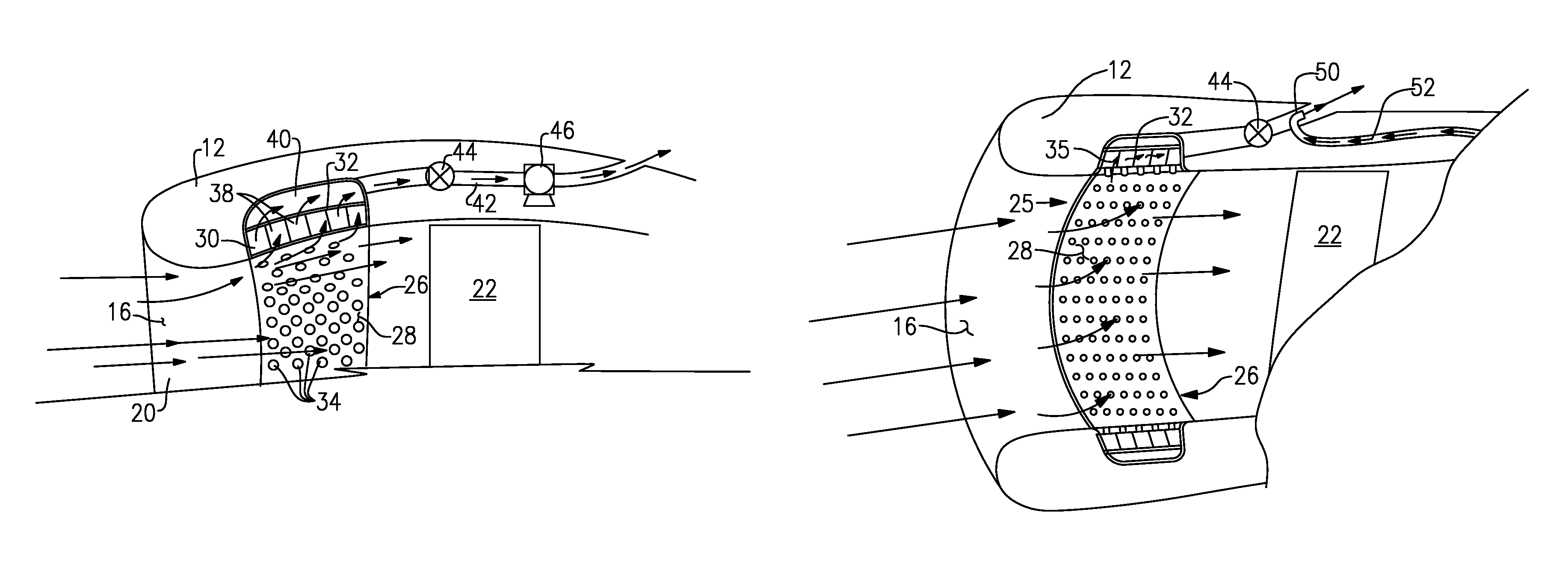
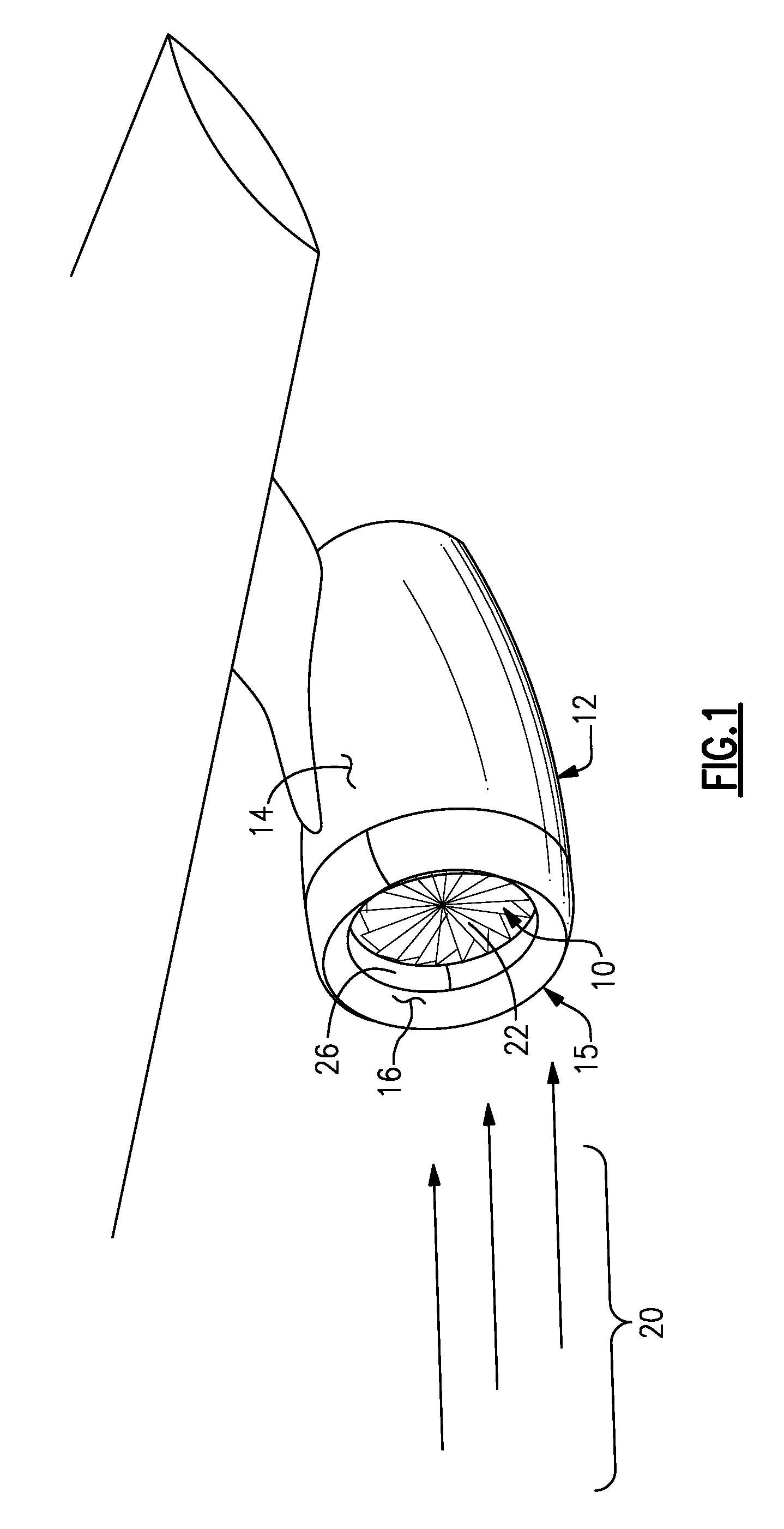
[0013]Referring to FIG. 1, a gas turbine engine assembly 10 is disposed within a nacelle 12. The nacelle 12 includes an outer surface 14 and an inner surface 16. A leading edge 15 defines an inlet surface for airflow 20. Air flow 20 into the nacelle 12 is directed towards a fan 22 of the gas turbine engine assembly 10. The inner surface 16 is comprised of a plurality of panels 26 that provide for the attenuation of sound energy generated by the gas turbine engine 10. Although an under wing mounted nacelle 12 is illustrated by way of example, other nacelle mounting configurations such as for example fuselage mounted, over wing mounted, and even embedded within a fuselage or wing, will also benefit from the disclosed features.

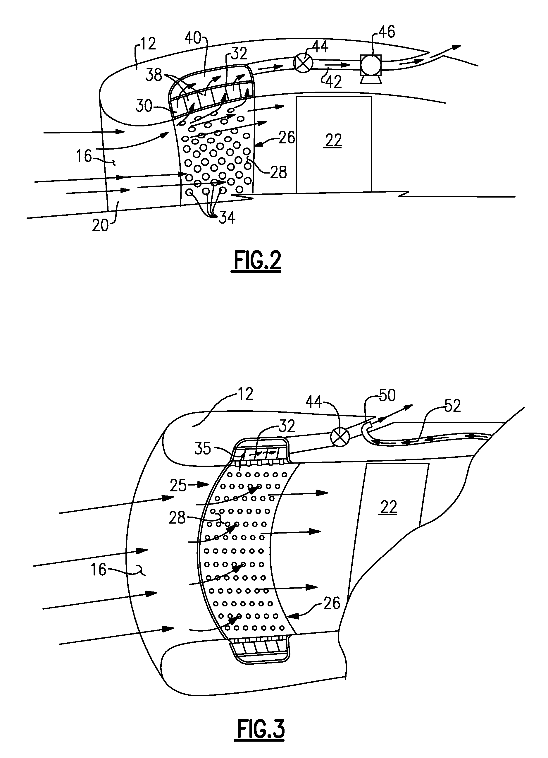
[0014]Referring to FIG. 2, the example nacelle 12 includes a panel 26 comprised of a face sheet 28 that covers a noise attenuation layer 30. The noise attenuation layer is comprised of a plurality of cells 38. The cells 38 provide for the dissipation of sound ene...


PUM


Abstract

An inlet flow control system disposed within a nacelle includes a panel on an inner surface of that nacelle. The panel includes a noise attenuation layer that dissipates noise energy. A vacuum source generates a pressure differential across the noise attenuation layer for drawing airflow through the panel and away from an inner surface of the nacelle.

Description

BACKGROUND OF THE INVENTION[0001]This invention generally relates to an air inlet control system for a gas turbine engine.[0002]Operation of a gas turning engine requires intake of air for the combustion process. Incoming air is directed into the engine by a nacelle that defines a leading edge and an intake opening for incoming air. During most operating conditions air flow along the interior surface of the nacelle is turbulent resulting in a thin boundary layer. However, in some instances such as during low speed high power operation and high angle of attack, local flow fields result in an increase in boundary layer thickness along the surface of the nacelle. At certain airflows the thickened boundary layer can separate from the inner surface of the nacelle creating vortices and non-uniform air flows. These non-uniform air flows and vortices hamper performance of the gas turbine engine.[0003]Accordingly, it is desirable to develop and design a system that prevents build-up of bound...

Claims


Application Information

Patent Timeline
Patent Type & Authority Patents(United States)
IPC IPC(8): B64C21/06
CPCB64D33/02F02C6/08F02C7/045F02K3/06B64D2033/0206B64D2033/0226F05D2260/96
Inventor CLOFT, THOMAS G.WILEY, RICHARD H.
Owner RAYTHEON TECH CORP
Why Eureka
Try Eureka