Precise fabrication of polymer microlens arrays

a technology of polymer microlens and arrays, which is applied in the direction of instruments, photomechanical equipment, paper/cardboard containers, etc., can solve the problems of invention and placement of arrayed microlenses relative to light sources, and achieve excellent uniformity and tight alignment tolerances

Inactive Publication Date: 2010-08-10
RGT UNIV OF CALIFORNIA
View PDF7 Cites 6 Cited by
  • Summary
  • Abstract
  • Description
  • Claims
  • Application Information

AI Technical Summary

Benefits of technology

[0068]Being that, to the best knowledge of the inventors, they are the first to employ dip-coating in a hydrophobic process for the production of microstructures including microlenses, they are the first to recognize that control of the substrate withdrawal speed, and dipping angle, monomer viscosity, surface tension, density, and index of refraction, and the array fill-factor, and the surface-free-energies of the hydrophilic and hydrophobic areas will permit control of the f# of microlenses. Indeed, the same substrate can be withdrawn slowly at one time and quickly at another so as to create microlenses of dramatically different f# immediately adjacent to each other.
[0069]Moreover, the invention still further contemplates that multiple dip-coats can be used to improve lens performance; a “faster” lens with a lower f# resulting from multiple dipping / curing cycles. Clearly if only a portion of a substrate is re-dipped than only the microlenses of that portion will augmented.
[0070]The microlenses so precision fabricated are useful. They can be fabricated with a range of f#s (with a plano-convex minimum of f / 1.38), excellent surface profiles (maximum deviation from a sphere was <±5 nm over the center 130 μm of 500 μm diameter f / 3.2 microlenses), and are stable at room temperature.
[0071]Fabrication of the microlenses is well controlled, and the microlenses so fabricated are of uniform high quality. An optimum withdrawal speed was identified at which (i) the f# of each microlens was minimized while (ii) uniformity of all microlens in the array was maximized. At this optimum speed arrays of f / 3.48 microlenses were fabricated using one dip-coat with uniformity better than Δf / f˜±3.8%. Multiple dip-coats allowed production of f / 1.38 microlens arrays and uniformity better than Δf / f˜±5.9%. Average f#s were reproducible to within 3.5%.
[0079]Regardless of which method is used to transfer liquid to the substrate, the liquid clings to the hydrophilic areas, and forms caps of liquid under the influence of surface tension. These caps will adopt a shape that minimizes their free energy.
[0084]Because the microlenses are self-aligned, low f# microlenses that would otherwise require tight alignment tolerances can be integrated with ease. As an example, f / 1.55 microlenses with smooth surface profiles, deviating from spherical by just ±15 nm, have been integrated on SMF optical fiber. Arrays of such microlenses having excellent uniformity (Δf / f˜5.9% for a 15×15 array of 500 μm f / 1.4 microlenses), stability, and reproducibility (average f#s are reproducible to within 3.5%) can be fabricated with massive parallelism.4.1 Detail Method of Fabricating a Microlens Precision Sized, Aligned and Spatially Positioned to a Small Light Source

Problems solved by technology

However, the location and alignment of the arrayed microlenses relative to the light sources—as will be taught by the present invention—is problematic.

Method used


Image

  • Precise fabrication of polymer microlens arrays
  • Precise fabrication of polymer microlens arrays
  • Precise fabrication of polymer microlens arrays

Examples


Embodiment Construction

[0126]The following description is of the best mode presently contemplated for the carrying out of the invention. This description is made for the purpose of illustrating the general principles of the invention, and is not to be taken in a limiting sense. The scope of the invention is best determined by reference to the appended claims.

[0127]Although specific embodiments of the invention will now be described with reference to the drawings, it should be understood that such embodiments are by way of example only and are merely illustrative of but a small number of the many possible specific embodiments to which the principles of the invention may be applied. Various changes and modifications obvious to one skilled in the art to which the invention pertains are deemed to be within the spirit, scope and contemplation of the invention as further defined in the appended claims.

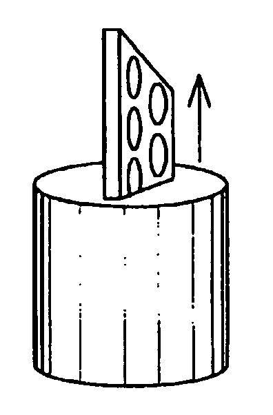
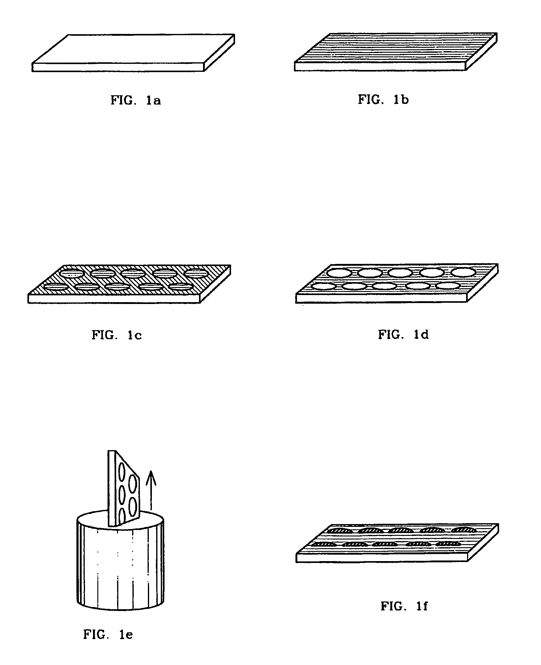
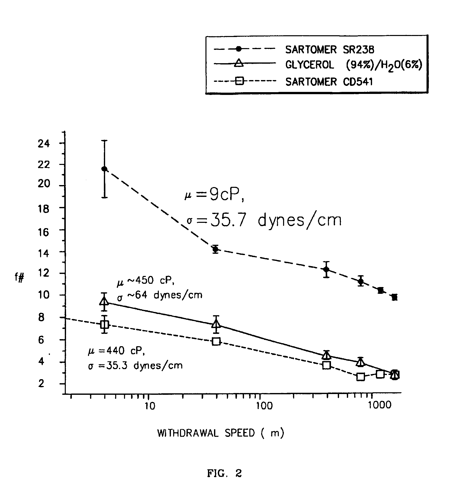
1. Fabrication of Microlens Arrays

[0128]In accordance with the present invention, large and uniform arrays of m...


PUM

PropertyMeasurementUnit
viscosityaaaaaaaaaa
wavelengthaaaaaaaaaa
diametersaaaaaaaaaa

Abstract

High performance microlens arrays are fabricated by (i) depositing liquid on the hydrophilic domains of substrates of patterned wettability by either (a) condensing liquid on the domains or (b) withdrawing the substrate from a liquid solution and (ii) optionally curing the liquid to form solid microlenses. The f-number (f#) of formed microlenses is controlled by adjusting liquid viscosity, surface tension, density, and index of refraction, as well as the surface free energies of the hydrophobic and hydrophilic areas. The f-number of formed microlenses is also adjustable by controlling substrate dipping angle and withdrawal speed, the array fill factor and the number of dip coats used. At an optimum withdrawal speed f# is minimized and array uniformity is maximized. At this optimum, arrays of f / 3.48 microlenses were fabricated using one dip-coat with uniformity better than Δf / f˜±3.8% while multiple dip-coats permit production of f / 1.38 microlens arrays and uniformity better than Δf / f˜±5.9%. Average f#s are reproducible to within 3.5%. The method is adaptable and extendible to precision parallel fabrication of (i) microlenses precisely sized, aligned and spatially positioned to various small light sources and optical fiber ends, (ii) conductive bump bonds on substrate pads, and (iii) conductive bonds between corresponding domains on separate perpendicular substrates, all of which are self-aligned.

Description

RELATION TO A PROVISIONAL PATENT APPLICATION[0001]The present patent application is descended from, and claims benefit of priority of, U.S. provisional patent application Serial No. 60 / 184,605 filed on Feb. 24, 2000, for LOW COST, ACCURATE PATTERNING OF HYDROPHOBIC MATERIALS TO ALLOW THE ASSEMBLY OF ORGANIC AND INORGANIC COMPONENTS ON A SUBSTRATE to the selfsame inventors as the present patent application.[0002]This invention was made by support of the U.S. Government under Grant No. DARPA-HOTC MDA 972-98-1-0001 (Defense Advanced Research Project Agency—Heterogeneous Optoelectronic Technology Center) acting through the United States Defense Advanced Research Project Agency (DARPA). The U.S. Government has certain rights in this invention.BACKGROUND OF THE INVENTION[0003]1. Field of the Invention[0004]The present invention generally concerns (i) microstructures including optical microlenses and electrical bump bonds; (ii) liquids (and especially liquid monomers that may be cured to f...

Claims


Application Information

Patent Timeline
Patent Type & Authority Patents(United States)
IPC IPC(8): B29D11/00G02B3/00G03F7/00
CPCB29D11/00365B82Y10/00B82Y40/00G02B3/0018G03F7/0002G02B3/0012Y10T156/10G02B3/0056
Inventor HARTMANN, DANIEL M.ESENER, SADIK C.KIBAR, OSMAN
Owner RGT UNIV OF CALIFORNIA
Why Eureka
Try Eureka