Mirror structure and laser device comprising such a mirror structure

a mirror structure and laser device technology, applied in the direction of lasers, optical resonator shape and construction, instruments, etc., can solve the problems of incompatible low-cost batch manufacturing technology, inability to solve the problem of spatial coherence of emitted beams, and increasing the emission area, so as to achieve efficient solution

Inactive Publication Date: 2010-08-17
UNIV JEAN MONNET
View PDF12 Cites 82 Cited by
  • Summary
  • Abstract
  • Description
  • Claims
  • Application Information

AI Technical Summary

Benefits of technology

[0007]An object of the invention is to provide a laser device which efficiently solves the problem of poor spatial coherence, in particular for high power, wide area surface emitting lasers.
[0011]Thus, the present invention concerns a laser mirror structure intended to define a laser cavity and comprising a multilayer and a resonant grating mirror formed by a grating associated with a waveguide, characterized in that said resonant grating mirror and said multilayer are arranged for acting together as a transverse mode selector of the laser cavity, the resonant grating mirror being highly reflective only for a narrow angular spectrum centered at a given incidence angle so that this resonant grating mirror defines an angularly selective mirror, said multilayer being arranged for adjusting the reflectivity of the laser mirror structure over a broad angular spectrum including said narrow angular spectrum, this reflectivity being selected so as to allow the lasing in said laser cavity of a determined transverse mode having substantially its angular spectrum contained in said narrow angular spectrum of said resonant grating mirror but to prevent the lasing of higher modes having their angular spectrum substantially wider than said narrow angular spectrum.
[0012]The object of the present invention is thus neither the control of the polarization nor the control of the longitudinal mode spectrum of a laser. Its object is to impose the single transverse mode lasing of a surface emitting laser by preventing the lasing of the higher order transverse modes which would otherwise be naturally generated.
[0013]There are two embodiments of the present invention which relate to the presence and the relative importance of thermal lens effect in the laser cavity. In the presence of weak thermal lens effect, the reflective angular filtering action of the resonant grating mirror of the mirror structure does not have to be strong to impose the lasing of the fundamental transverse mode of the laser cavity, therefore the transverse mode selective reflection which it provides is advantageously completed by a multilayer exhibiting high reflection. In the presence of high gain active material and strong thermal lensing effect, the reflective angular filtering action of the resonant grating mirror of the mirror structure has to be strong enough to impose the lasing of the fundamental transverse mode.

Problems solved by technology

However, a problem occurs by increasing the emission area because the spatial coherence of the emitted beam decreases.
Such solution is not compatible with low cost batch manufacturing technologies.
Such solution is difficult to realize technologically and represents a strong perturbation of the whole VCSEL structure.
Consequently, mode size in the order of several hundreds of μm is required, but this is impossible to obtain with current state-of-the-art microchip lasers.

Method used


Image

  • Mirror structure and laser device comprising such a mirror structure
  • Mirror structure and laser device comprising such a mirror structure
  • Mirror structure and laser device comprising such a mirror structure

Examples


first embodiment

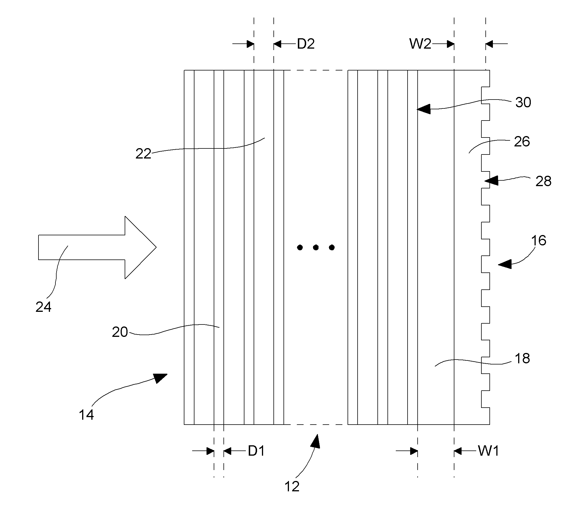
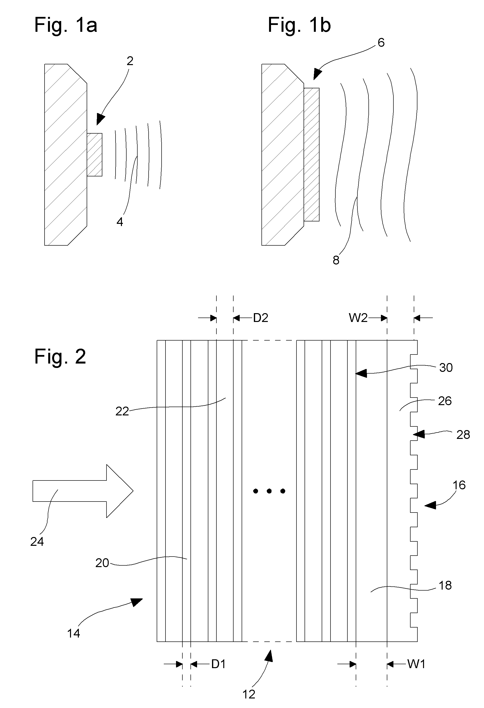
[0039]For differentiating the reflection coefficient of the plane waves of beam 24 having close to normal angular spectral components from those plane waves having oblique angular spectral components, on the one hand, the inherently wide angular spectrum multilayer reflective mirror 14 is arranged for reflecting a major part but not substantially all of the power of the incident beam 24, preferably in the range 80% to 98% and in particular in the range 90% to 97%. On the other hand, the resonant grating mirror 16 is arranged for providing quasi total resonant reflection of the power transmitted by the multilayer mirror for a narrow angular spectrum around the normal as disclosed in document by I. A. Avrutsky and V. A. Sychugov: “Reflection of a beam of finite size from a corrugated waveguide”, Journal of Modern Optics, Vol. 36, 1989, p. 1527. By so doing, the advantages of both mirrors are combined: usual multilayer mirrors can exhibit close to 100% reflectivity but they are only we...

second embodiment

[0057]In a laser cavity of the second embodiment shown in FIG. 7 the waveguide grating mirror 16 is used as a front mirror to provide an unstable resonator of relatively low quality factor. Multilayer 14 is an antireflection multilayer. Buffer layer 18 must simply be large enough to isolate the coupled waveguide mode in layer 26 from multilayer 14 and especially from the active zone which can have a refractive index larger than the waveguide mode effective index. Other references already described will not be described again.

[0058]In case where the mirror structure of the invention is placed in the near field of the emitted wave, at a distance which is much smaller than the Fresnel distance and the active medium has a positive or negative thermal lensing effect, as it can be the case in microchip lasers, the incident wave has significantly larger angular width than the angular width of the waveguide mode achieving resonant reflection and said wave therefore partially transmits throu...


PUM


Abstract

For increasing the power emitted by surface emitting lasers and for improving the spatial coherence of the laser beam, emitted in particular by disk lasers, microchip lasers and VCSELs having a relatively wide emitting area, the invention proposes to select a low order transverse cavity mode by means of a mirror structure (12) of high reflectivity, and of high angular selectivity. The mirror structure comprises a multilayer (14) receiving the optical beam (24) and a resonant grating mirror (16) following the multilayer and arranged for highly reflecting the optical beam in a narrow angular range at each side of a determined incidence angle.

Description

[0001]This is a National Phase Application in the United States of International Patent Application No. PCT / EP2006 / 070199 filed Dec. 22, 2006, which claims priority on European Patent Application No. 05292786.0, filed Dec. 22, 2005. The entire disclosures of the above patent applications are hereby incorporated by reference.FIELD OF THE INVENTION[0002]The present invention concerns a mirror structure which is angularly selective. The present invention also concerns laser devices equipped with such a mirror structure for selecting the fundamental transverse cavity mode and thus improving the spatial coherence of these devices. In particular, the present invention concerns VCSELs, disk lasers and microchip lasers.BACKGROUND OF THE INVENTION[0003]Laser devices having an active medium of small length like disk lasers, microchip lasers or VCSELs (Vertical Cavity Surface Emitting Laser) or surface emitting organic material lasers emit an optical power which is substantially proportional t...

Claims


Application Information

Patent Timeline
Patent Type & Authority Patents(United States)
IPC IPC(8): H01S3/08G02B5/18
CPCG02B5/0833G02B5/085G02B5/1814H01S3/08059H01S3/0604H01S5/105H01S5/18319H01S2301/166H01S5/11
Inventor PARRIAUX, OLIVIERTISHCHENKO, ALEXANDRELYNDIN, NIKOLAYBISSON, JEAN-FRANCOIS
Owner UNIV JEAN MONNET
Why Eureka
Try Eureka