
Compacting test responses using X-driven compactor

a compactor and compactor technology, applied in the field of scanning-based design and testing using designfortest (dft) techniques, can solve problems such as destroying the signature, unable to repair, and aliasing, and achieve the effects of minimizing x-masking and/or alising, and minimizing x-induced masking and error masking

Inactive Publication Date: 2010-08-17
SYNTEST TECH
View PDF5 Cites 12 Cited by
  • Summary
  • Abstract
  • Description
  • Claims
  • Application Information

AI Technical Summary

Benefits of technology

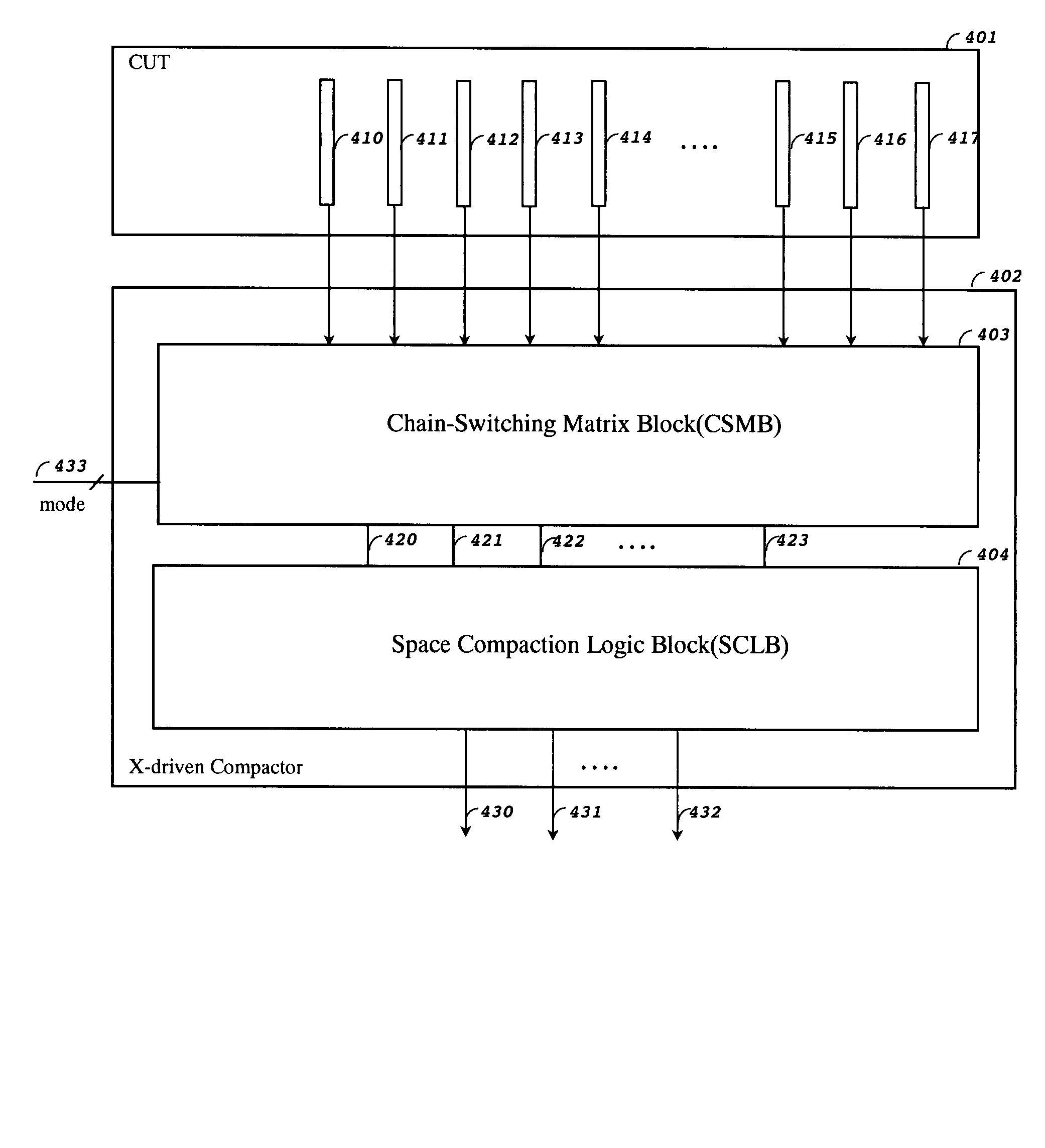
[0012]The objective of the present invention is to provide an improved X mask-free Space compactor, named X-driven compactor, which advantageously minimizes X-induced masking and error masking. The X-driven compactor has the ability to switch scan chains to become driver chains for specific Space compactor cones. With the switching capability, a fault effect expected to be masked by the X-masking scan cell—has a better chance propagating to X-driven compactor outputs for observation by switching the relevant X-masking scan chain to become the driver chain for a Space compactor cone not assigned (off-duty) to observe the fault effects. Similarly, if error masking is expected to occur in the Space compactor, switching one or more of the Aliasing scan chains to be driver chains for another off-duty Space compactor cone can also minimize error masking. The aforementioned switching mechanism that minimizes X-masking and / or Alising is herein categorizingly named “X-driven switching”. Dynamic X-driven switching by switching X-masking and / or Aliasing scan chains to become driver chains for off-duty Space compactor cones at relevant shift cycles can dramatically minimize X-induced masking and Aliasing, thus allowing fault effects to be observed and fault coverage increases accordingly.

Problems solved by technology

However, some X's, like races, may become known very late at the design or manufacturing stage, and thus cannot be repaired.
Since a time compactor is LFSR-based with output feeding back to its inputs, once an X value is injected, the X will stay in the compactor and thus destroy its signature.
If two or more scan cells with captured fault effects are compacting in step but eventually the fault effects cancel each other out during compaction, the problem is called Error masking (Aliasing).
The circuit's fault coverage might decrease due to X-induced masking and Error masking when a compactor is used.
This compactor, however, cannot tolerate circuits with many X values appearing at the scan channels.
However, this compactor needs additional registers (storage elements) and decoding logic to block X-value propagation.
However, it needs many additional input pins to select scan chain outputs.
It also reduces the ATPG dynamical compaction ability because only a small fraction of scan outputs can be used for observation.
The compactor has limited X tolerant ability since X-values that are fed into the compactor can be clocked out after a finite clock cycles.

Method used


Image

  • Compacting test responses using X-driven compactor
  • Compacting test responses using X-driven compactor
  • Compacting test responses using X-driven compactor

Examples


Embodiment Construction

[0023]The following description is presently contemplated as the best mode of carrying out the present invention. This description is not to be taken in a limiting sense but is made merely for the purpose of describing the principles of the invention. The scope of the invention should be determined by referring to the appended claims.

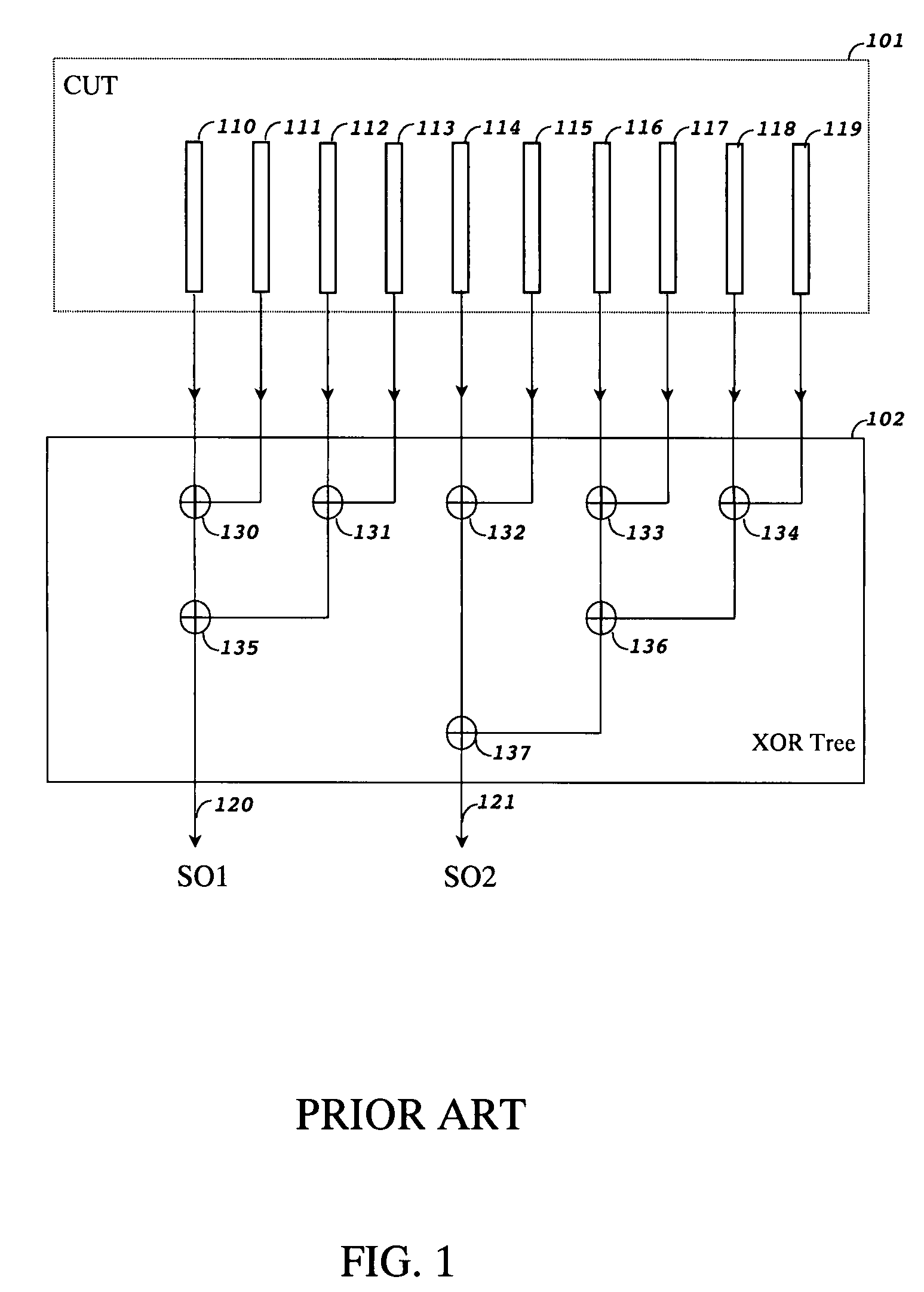
[0024]FIG. 1 shows a circuit diagram of a prior art system that includes multiple scan chains 110-119 in a circuit-under-test (CUT) 101 and a Space compactor built with an Exclusive-OR (XOR) tree. The outputs of multiple scan chains 110-119 feed to a Space compactor 102 built with XOR gates 130-137. The results from the Space compactor become compressed test responses SO1-SO2120-121, which are then compared with expected test responses to determine the pass / fail status of the CUT 101.

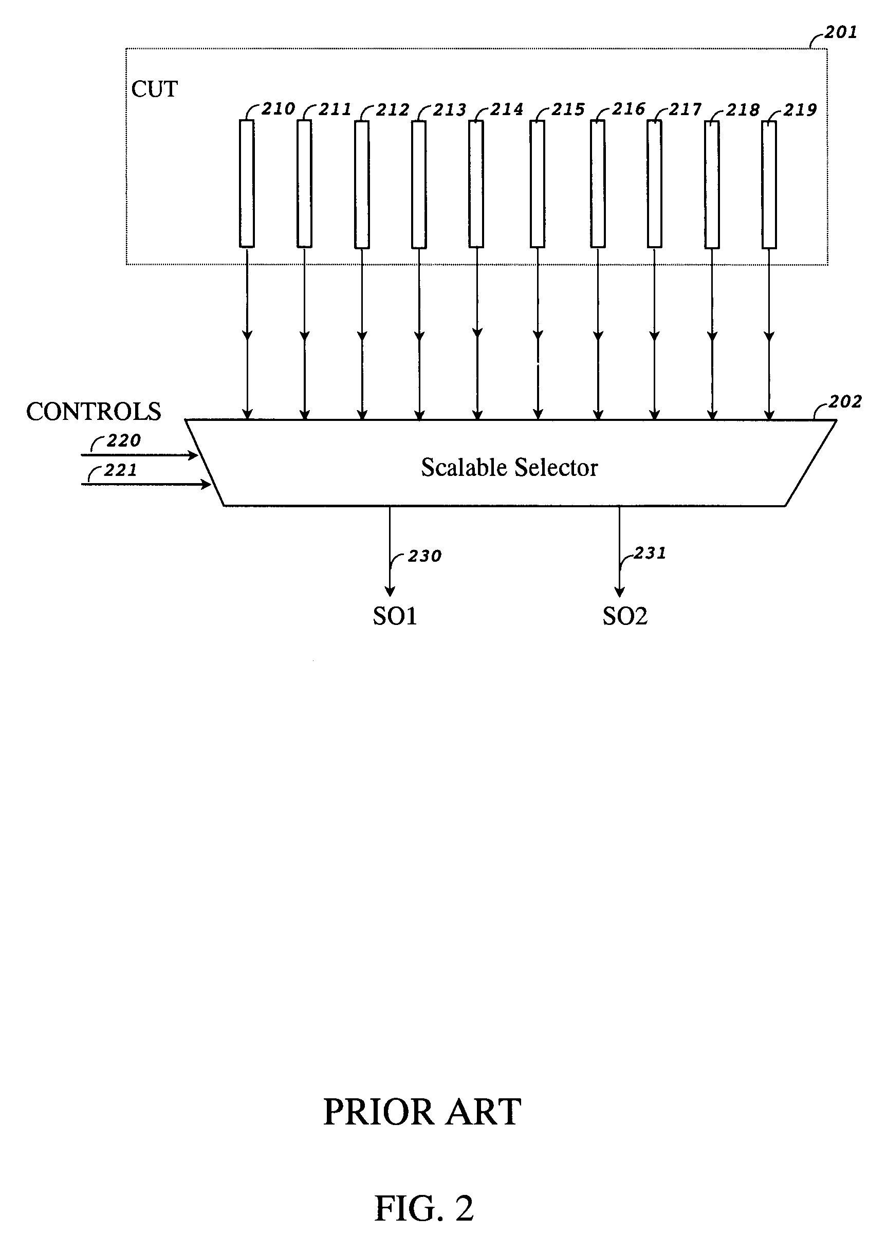
[0025]FIG. 2 shows a circuit diagram of a prior art system that includes multiple scan chains 210-219 in a circuit-under-test (CUT) 201 and a Space compactor built with a s...


PUM


Abstract

A method and apparatus for compacting test responses containing unknown values in a scan-based integrated circuit. The proposed X-driven compactor comprises a chain-switching matrix block and a space compaction logic block. The chain-switching matrix block switches the internal scan chain outputs before feeding them to the space compaction logic block for compaction so as to minimize X-induced masking and error masking. The X-driven compactor further selectively includes a finite-memory compaction logic block to further compact the outputs of the space compaction logic block.

Description

REFERENCE TO RELATED APPLICATIONS[0001]This application claims the benefit of and priority of Provisional Application No. 60 / 844,390, filed Sep. 14, 2006 entitled COMPACTING TEST RESPONSES USING X-DRIVEN COMPACTOR.FIELD OF THE INVENTION[0002]The present invention generally relates to the field of scan-based design and test using design-for-test (DFT) techniques. Specifically, the present invention relates to the field of scan testing and test compression.BACKGROUND[0003]As integrated circuits increase in size and complexity, test compression is becoming a requirement for reducing test data volume and test application time. Test compression compresses the amount of both stimuli and response data that must be stored in an automatic test equipment (ATE).[0004]Test stimulus compression is done by adding a decompressor at the scan input side of the scan chains for decompressing n-input compressed test patterns stored in the ATE to m-input decompressed test patterns for driving m internal...

Claims


Application Information

Patent Timeline
Patent Type & Authority Patents(United States)
IPC IPC(8): G01R31/28
CPCG01R31/318547
Inventor WANG, ZHIGANGWANG, LAUNG-TERNG L.-T.WU, SHIANLINGWEN, XIAOQINGSHEU, BORYAUJIANG, ZHIGANG
Owner SYNTEST TECH
Learn More