Control method combining fuzzy logic control with sliding mode control for ideal dynamic responses

a control method and fuzzy logic technology, applied in adaptive control, process and machine control, instruments, etc., can solve the problems of hydrostatics, high cost, short travel, etc., and achieve the effect of effective control power, low cost and high precision

Active Publication Date: 2010-08-24
NAT TAIWAN UNIV OF SCI & TECH
View PDF4 Cites 16 Cited by
  • Summary
  • Abstract
  • Description
  • Claims
  • Application Information

AI Technical Summary

Benefits of technology

[0009]In response to the need of positioning in the industry and consideration of working stage cost, the present invention provides an improved control method combining fuzzy logic control with sliding mode control, which is utilized in a low cost 2D servo positioning stage to meet the industry requirements of low-price but high precision. The improved control method provides effective control power and provides the 2D servo positioning stage with quick transient response capability without producing overshoot.
[0010]In a first aspect, the present invention provides a control method combining fuzzy logic control with sliding mode control, which is adapted for receiving an input signal and obtaining an output signal corresponding to the input signal through sliding mode parameter definition and fuzzy logic inference, wherein the input signal is denoted as e(t) representing for an error between a practically measured stage displacement and a desired displacement, a signal ce(t) representing for an error change amount is obtained from the input signal e(t), sliding variables are defined as s(t)=ce(t)+λe(t) and are used as input control variables of fuzzy control prior to fuzzification, the output signal is servo mechanism drive power u(t) for driving the servo mechanism to move the stage, and wherein the value of λ is designed according to convergence rates of the two variables e(t) and ce(t). Using the control method, 2D fuzzy control rule is simplified into 1D fuzzy control rule through the sliding variable defined by the sliding mode, thus enhancing the computing efficiency and reducing computing resource.
[0012]Using the above variable membership function gain tuning method, the present invention makes improvement on the convention methods in which the gain is fixed, and quickly narrows the membership function scope by combining the input variable with the exponential function and the linear function. In addition, control with quick transient response and good steady state error range can be achieved. Moreover, the output of the control power has no excessive jitters, which greatly reduces the wastage of power.

Problems solved by technology

However, the lead screw positioning stage can only reach micro-positioning and are unable to provide nano-positioning capability due to some of its mechanical characteristics, such as backlash problem.
Therefore, conventional positioning stages with nano-positioning capability are all of Piezo-actuation, magnetic levitation or hydrostatics, which are expensive and have a short travel.
Currently, a most common method of traditional positioning system is to use a PID controller, which is advantageous in uncomplicated computation, but unable to meet high precision positioning control requirements.
However, this method requires a substantial computation resource and a long computation time, which makes the control device prohibitively expensive.
However, this Taiwan patent covers only improvements in the defuzzification part, and thus cannot achieve a higher speed of the overall computation.
However, this controller needs to perform many complicated computation steps and, when used in practice, still consumes a lot of computation resources and time.
As such, applying this fuzzy controller to precise positioning can be still difficult.
Having acknowledgement of the indispensability of the precision positioning stages and deficiency of various control methods, shortcomings need to be solved can be summarized as follows: (1) to reach high precision positioning, expensive positioning stages are required, making the positioning not cost-effective in practice; (2) if complicated control methods are used, then the computation time is increased and the hardware device is large in size, which is unpractical in use; and (3) the traditional control methods cannot achieve both quick transient response and steady state precise positioning.

Method used


Image

  • Control method combining fuzzy logic control with sliding mode control for ideal dynamic responses
  • Control method combining fuzzy logic control with sliding mode control for ideal dynamic responses
  • Control method combining fuzzy logic control with sliding mode control for ideal dynamic responses

Examples


Embodiment Construction

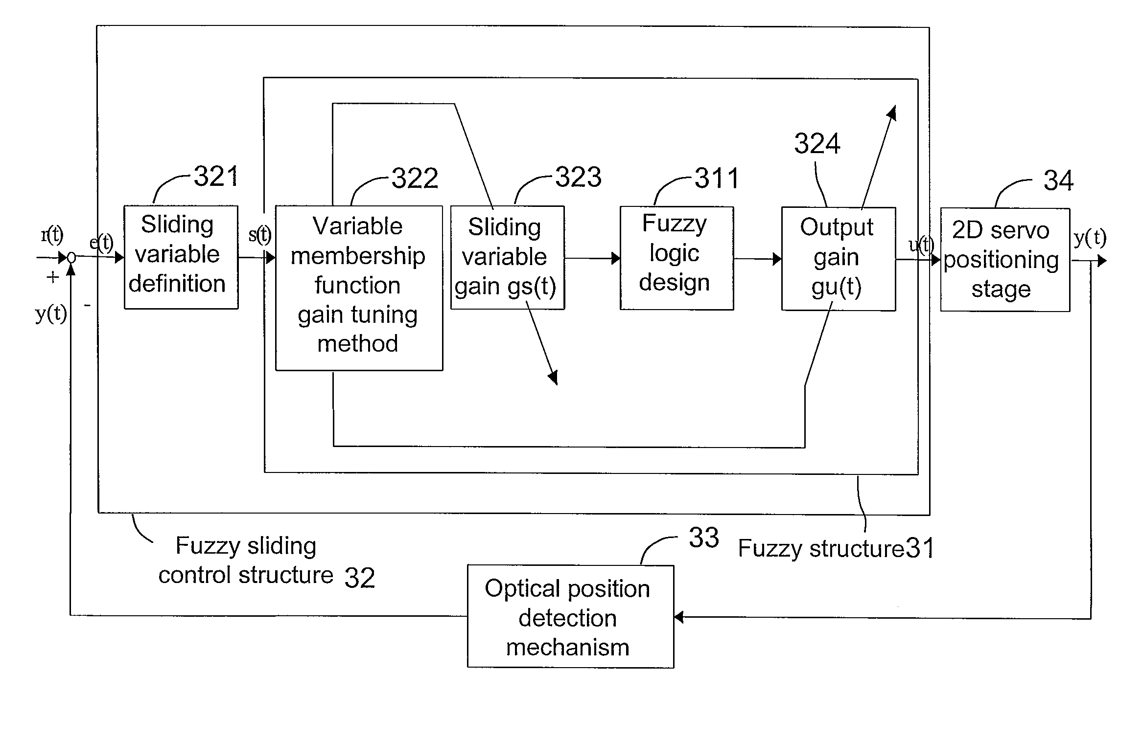
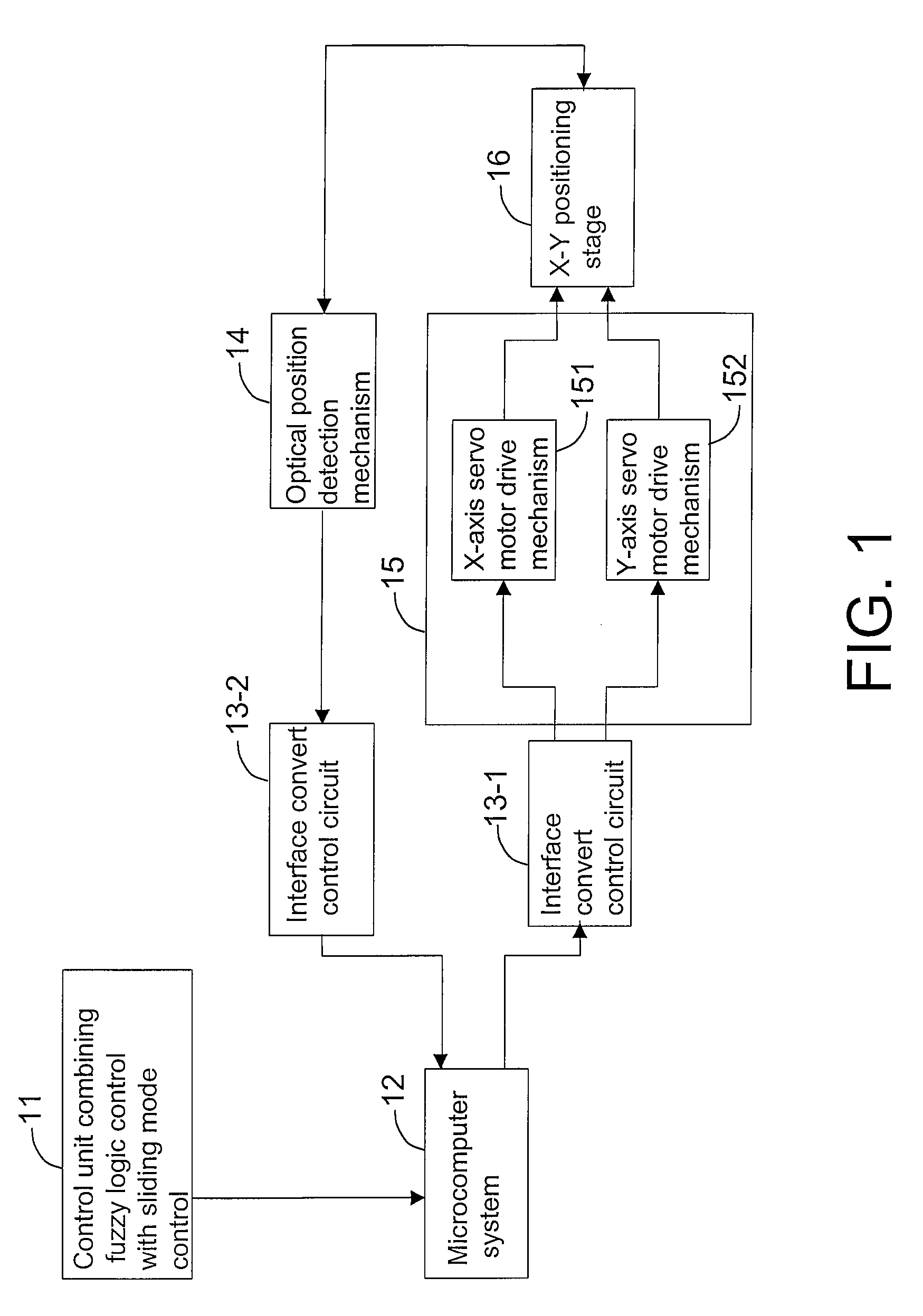
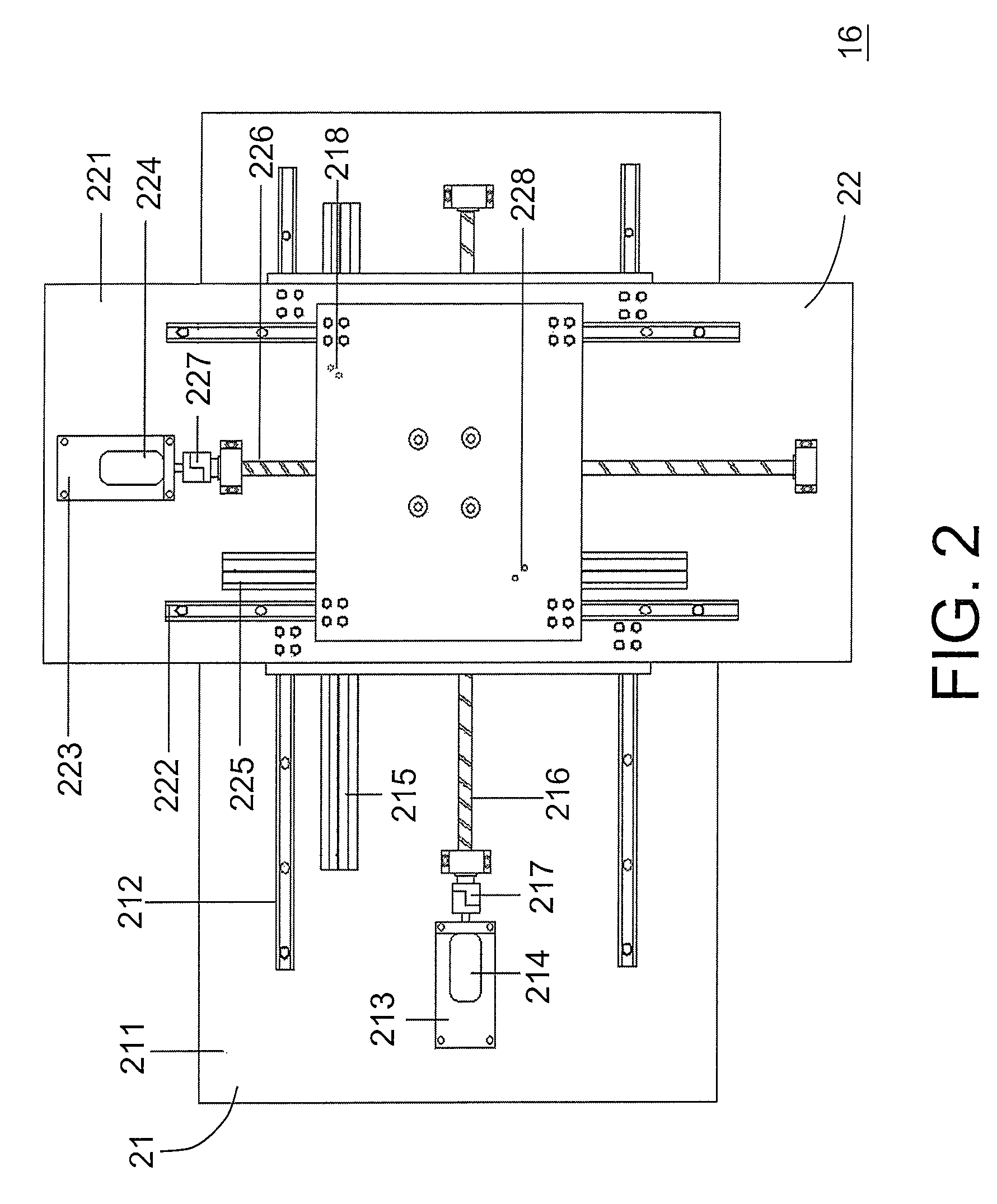
[0021]The present invention provides a control apparatus combining fuzzy logic control with sliding mode control and control method thereof. Referring to FIG. 1, which illustrates a block diagram of the control apparatus according to an embodiment of the present invention, the control apparatus 10 mainly includes a control unit combining fuzzy logic control with sliding mode control 11, a microcomputer system 12, an interface convert control circuit (e.g., AD / DA converter) 13-1, 13-2, an optical position detection mechanism 14, a servo motor drive mechanism 15, and a two-axis X-Y positioning stage 16 in which the present invention is applied. Software of the control unit 11 is programmed according to the improved control method of the present invention and loaded into the microcomputer system 12. The microcomputer system 12 is coupled to the servo motor drive mechanism 15 via the interface convert control circuit (e.g., DA converter) 13-1, thereby driving the X-Y positioning stage 1...


PUM


Abstract

The invention provides a novel control method combining fuzzy logic control with gain auto-tuning sliding mode control. A control error signal e(t) from the detection mechanism and an error change signal ce(t) are combined together as a sliding variable s(t)=ce(t)+λe(t) and used as the fuzzy input control variable. Using the control method, 2D fuzzy control rule is simplified into 1D fuzzy control rule through the sliding variable definition for enhancing the efficiency of computation and saving computation resources. Accordingly, both the quick transient response and steady state precision positioning can be achieved. The present method can overcome the disadvantages of current controller, which can not reach the desired transient and steady state responses simultaneously.

Description

CROSS-REFERENCE TO RELATED APPLICATION[0001]This application claims the priority benefit of Taiwan application serial no. 96107476, filed on Mar. 5, 2007. All disclosure of the Taiwan application is incorporated herein by reference.BACKGROUND OF THE INVENTION[0002]1. Field of the Invention[0003]The present invention generally relates to a fuzzy logic control apparatus and method, and more particularly, to an improved control method combining fuzzy logic control with sliding mode control, and also to application of the control method to a positioning mechanism which is a 2D servo positioning control device including a servo motor drive mechanism, a two-axis servo stage, a microcomputer control system, an interface convert control circuit, and an optical position detection mechanism. The positioning control method can not only be used with positioning control of 2D movement, but also be used in other fields such as positioning control of rotation or 3D movement.[0004]2. Description of...

Claims


Application Information

Patent Timeline
Patent Type & Authority Patents(United States)
IPC IPC(8): G06F15/18G05B13/02
CPCG05B13/0255G05B13/0275
Inventor HUANG, SHIUH-JERLIN, SHU-YIHE, GUANG-LING
Owner NAT TAIWAN UNIV OF SCI & TECH
Why Eureka
Try Eureka