Carbon foam structural insulated panel

a technology of structural insulation and carbon foam, applied in the direction of thin material processing, layered products, transportation and packaging, etc., can solve the problems of poor thermal insulation and resistance of structures, slow and labor-intensive approach, and lack of adequate thermal insulation properties, etc., to achieve high strength-to-density ratio, high resistance to combustion or charring, and easy machine

Inactive Publication Date: 2010-08-31
GRAFTECH INT HLDG INC
View PDF79 Cites 45 Cited by
  • Summary
  • Abstract
  • Description
  • Claims
  • Application Information

AI Technical Summary

Benefits of technology

[0016]The present invention provides a SIP which is uniquely capable of being used in applications requiring a high strength to density ratio, and / or high resistance to combustion or charring. The inventive carbon foam structural insulated panel exhibits a density, compressive strength and compressive strength to density ratio to provide a combination of strength and relatively light weight characteristics not heretofore seen. In addition, the carbon lattice work of the carbon foam resists both charring and combustion while maintaining structural integrity in other environmental conditions from high humidity to severely low temperatures. Furthermore, the carbon foam can be produced in a desired size and configuration and can be readily machined for a specific size for a structural insulated panel.
[0018]The inventive structural carbon foam panel should have the carbon foam core of a relatively uniform density both longitudinally and latitudinally for consistent thermal insulation and strength characteristics throughout the panel. Specifically, the carbon foam should have a relatively uniform distribution of pores in order to provide the required high compressive strength, the pores being relatively isotropic. In addition, the carbon foam core should have a total porosity of about 65% to about 95%, more preferably about 70% to about 95% to create the optimal strength to density ratio of the carbon foam structural insulated panel.
[0020]Prior to the addition of outerlayers, the carbon foam core can be treated with a variety of coatings to improve the overall performance of the carbon foam SIP. For example, an anti-oxidation coating can be applied to the carbon foam to increase the longevity of the SIP in highly oxidative conditions. Additionally, a fire retardant coating could also be applied to the carbon foam core to further increase the integrity of the carbon foam core and thus the SIP, when exposed to extreme temperatures.
[0026]Yet another object of the invention is a structural insulated panel foam which can be produced in a desired size and configuration, where the carbon foam core can be machined or joined with other similar carbon foam sheets to provide larger structural carbon foam panels.
[0028]Still another object of the invention is to provide a structural carbon insulated panel whereby the carbon foam core provides adequate thermal insulation to maintain a temperature differential between the exterior portion of the panel and the interior portion of the panel.

Problems solved by technology

While this type of building structure is well understood and possesses adequate strength, this approach is both slow and labor intensive.
Furthermore, these structures maintain poor insulation and resistance to environmental stresses such as moisture or insects.
For example, in Smith, U.S. Pat. No. 4,163,349, discloses an insulated building, though without adequate thermal insulating properties.
Unfortunately, SIPs produced by the prior art are not effective for many structural applications requiring high strength including high compressive strength values.
Furthermore, most SIPs claimed throughout the prior art are not effective against high heat or open flames, either combusting or experiencing significant charring.
In addition, the prior art SIPs generally lack a high strength to density ratio, making such SIPs ill suited for applications where a lightweight, insulating, yet strong panel is necessary for a building structure.

Method used


Image

  • Carbon foam structural insulated panel
  • Carbon foam structural insulated panel

Examples


Embodiment Construction

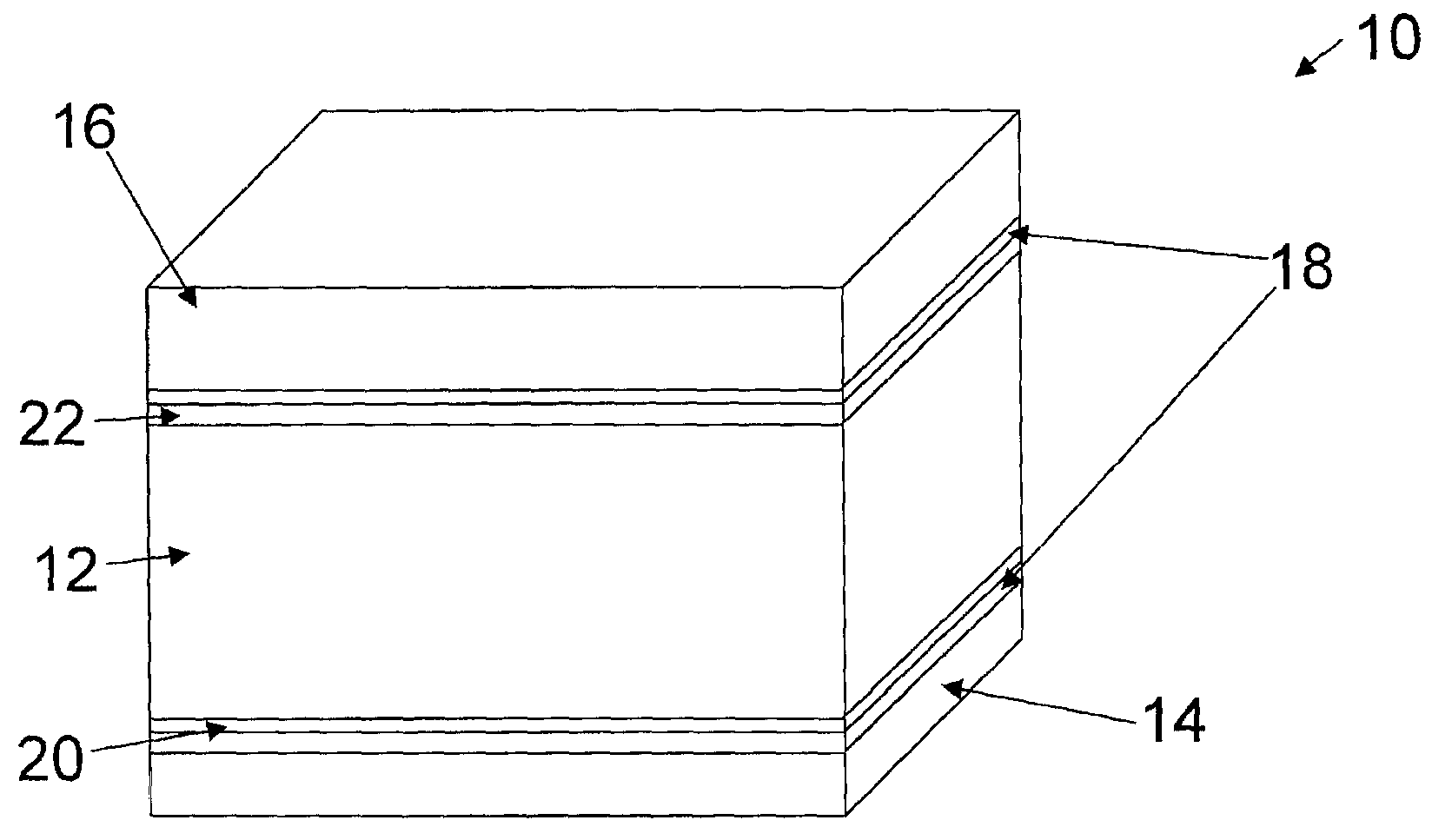
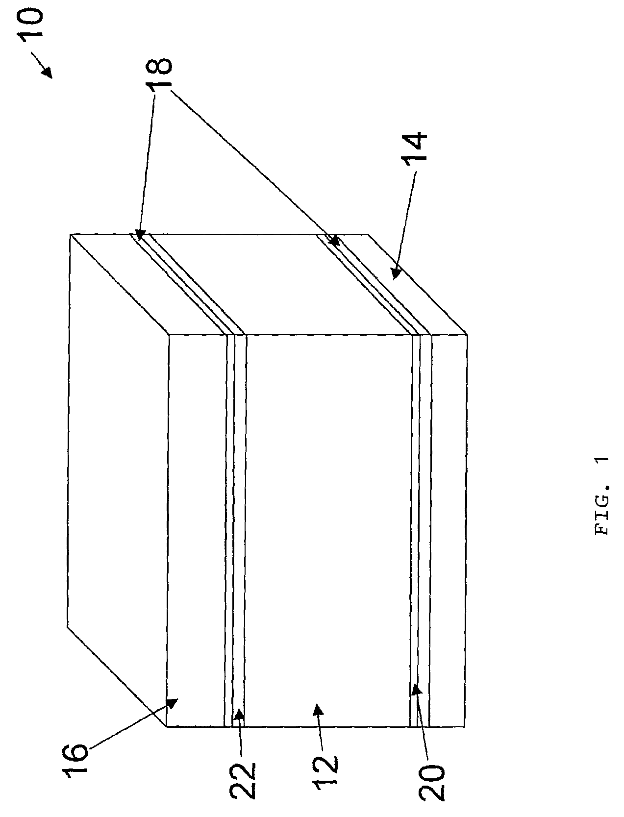
[0033]The carbon foam used as the core for the inventive panel exhibits a density, compressive strength and compressive strength to density ratio to provide a combination of strength and relatively light weight characteristics not heretofore seen. In addition, the monolithic nature and bimodal cell structure of the foam, with a combination of larger and smaller pores, which are relatively spherical, provide a carbon foam which can be produced in a desired size and configuration and which can be readily machined.

[0034]The carbon foam should have a relatively uniform distribution of pores in order to provide the required high compressive strength. In addition, the pores should be relatively isotropic, by which is meant that the pores are relatively spherical, meaning that the pores have, on average, an aspect ratio of between about 1.0 (which represents a perfect spherical geometry) and about 1.5. The aspect ratio is determined by dividing the longer dimension of any pore with its sho...


PUM

PropertyMeasurementUnit
liquid permeabilityaaaaaaaaaa
compressive strengthaaaaaaaaaa
diameteraaaaaaaaaa

Abstract

A structural insulated panel, which includes a carbon foam core having a high ratio of compressive strength to density, desirable fire retardant properties, and resistance to environmental stress. The carbon foam structural insulated panel also includes a first layer and a second layer bound to a first surface and second surface of the carbon foam core. Applications of the carbon foam structural insulated panel include structural and fire retardant elements of residential and commercial buildings, aircraft and also watercraft.

Description

RELATED APPLICATION[0001]This application is a continuation-in-part of commonly assigned U.S. patent application Ser. No. 11 / 314,975, entitled “Carbon Foam Structural Insulated Panel,” filed Dec. 21, 2005 now abandoned in the names of Douglas J. Miller, Yevgeniy Griffin and Mark Segger; commonly assigned U.S. patent application Ser. No. 10 / 970,352, now U.S. Pat. No. 7,527,855 entitled “High Strength Monolithic Carbon Foam,” filed Oct. 21, 2004 in the names of Douglas J. Miller, Irwin C. Lewis and Robert A. Mercuri, the disclosures of each of which are incorporated herein by reference.BACKGROUND OF THE INVENTION[0002]1. Technical Field[0003]The present invention relates to high strength structural panels useful for applications including the building construction of roofs, floors, walls, doors and other structures where a high strength-to-density ratio and improved fire retardant characteristics are useful. More particularly, the present invention relates to the use of carbon foam in...

Claims


Application Information

Patent Timeline
Patent Type & Authority Patents(United States)
IPC IPC(8): B32B9/00
CPCB32B5/18Y10T428/30
Inventor MILLER, DOUGLAS J.LEWIS, IRWIN C.MERCURI, ROBERT A.
Owner GRAFTECH INT HLDG INC
Why Eureka
Try Eureka