Lockout and monitoring system with SIL3 safety rating and method for lockout and monitoring

a technology of lockout monitoring and safety rating, applied in the field of conveyor systems, can solve the problems of wasting time and life, not providing the name or number, and therefore the location of the activated switch, and reducing the safety of the system

Active Publication Date: 2010-09-14
HUBBELL INC
View PDF18 Cites 7 Cited by
  • Summary
  • Abstract
  • Description
  • Claims
  • Application Information

AI Technical Summary

Benefits of technology

[0027]According to certain exemplary embodiments of the present invention, system and method for conveyor lockout and monitoring comply with the international IEC 61508 standard requiring fail safe hardware and software and a Safety Integrity Level (SIL) of 3, with 4 being the highest. The system and method facilitate stopping of the conveyor in an emergency situation and safely remote-isolating the conveyor for maintenance purposes, as well as system identifying the location along the conveyor of an activated emergency switch to generate a specific warning and automatically shutdown the conveyor.
[0029]According to yet other exemplary implementations of embodiments of the present invention, when a switch signaling an emergency stop is operated, a transmitter is turned ON and a separate transmitter is turned OFF resulting in a fail safe redundant switching system for the conveyor control circuit combined with accurate indication of the switch location.
[0030]According to exemplary implementations of embodiments of the present invention, a unique system with SIL 3 rating and method therefore provide not only fail safe stopping of the conveyor but also accurate indication of switch location that signaled the stopping.

Problems solved by technology

This type of system is subject to critical safety issues when simple electrical cable faults exist.Series connection of mushroom or lanyard operated stop switches with an end of line device to improve safety issues in the presence of simple electrical cable faults.
These conventional systems suffer from the problems of not providing the name or number, and therefore the location, of the activated switch.
Modern conveyors are typically exceeding 4,000 meters in underground installations and 10,000 meters in overland installations so the lack of information as to the location of the activated emergency stop switch or remote isolation switch can be costly in both lost time and loss of life.
Power is not generally available along the entire length of the conveyor, particularly long overland conveyors through often difficult remote terrain.
This lack of power makes location information providing monitoring systems even more difficult which is why most installations are limited to the simple series circuit system described above.
These are often difficult to monitor given the distances involved and the lack of power.
Conveyor installations are by their nature hostile environments for any electrical equipment and cabling that may be installed on their superstructure.
The equipment and particularly the cabling is subject to vibration, dust, falling material, rain, extremes in temperature and exposure to radiation all of which can result in the introduction of electrical faults that can compromise the integrity and safety of the conventional series connection monitoring systems described above.
None of the above-described patents or patent applications discloses a conveyor monitoring system where pulse width modulation and amplitude modulation are used for communication between field devices (such as remote isolation switches deployed at various locations of a conveyor belt) and a central controller, and for indication of the device location.
Furthermore, none of these patents or patent applications discloses a fail safe redundant switching system for a conveyor control circuit where additional transmitter and receiver modules are provided in combination with the means for accurate indication of switch location to achieve SIL 3 rating.

Method used


Image

  • Lockout and monitoring system with SIL3 safety rating and method for lockout and monitoring
  • Lockout and monitoring system with SIL3 safety rating and method for lockout and monitoring
  • Lockout and monitoring system with SIL3 safety rating and method for lockout and monitoring

Examples


Embodiment Construction

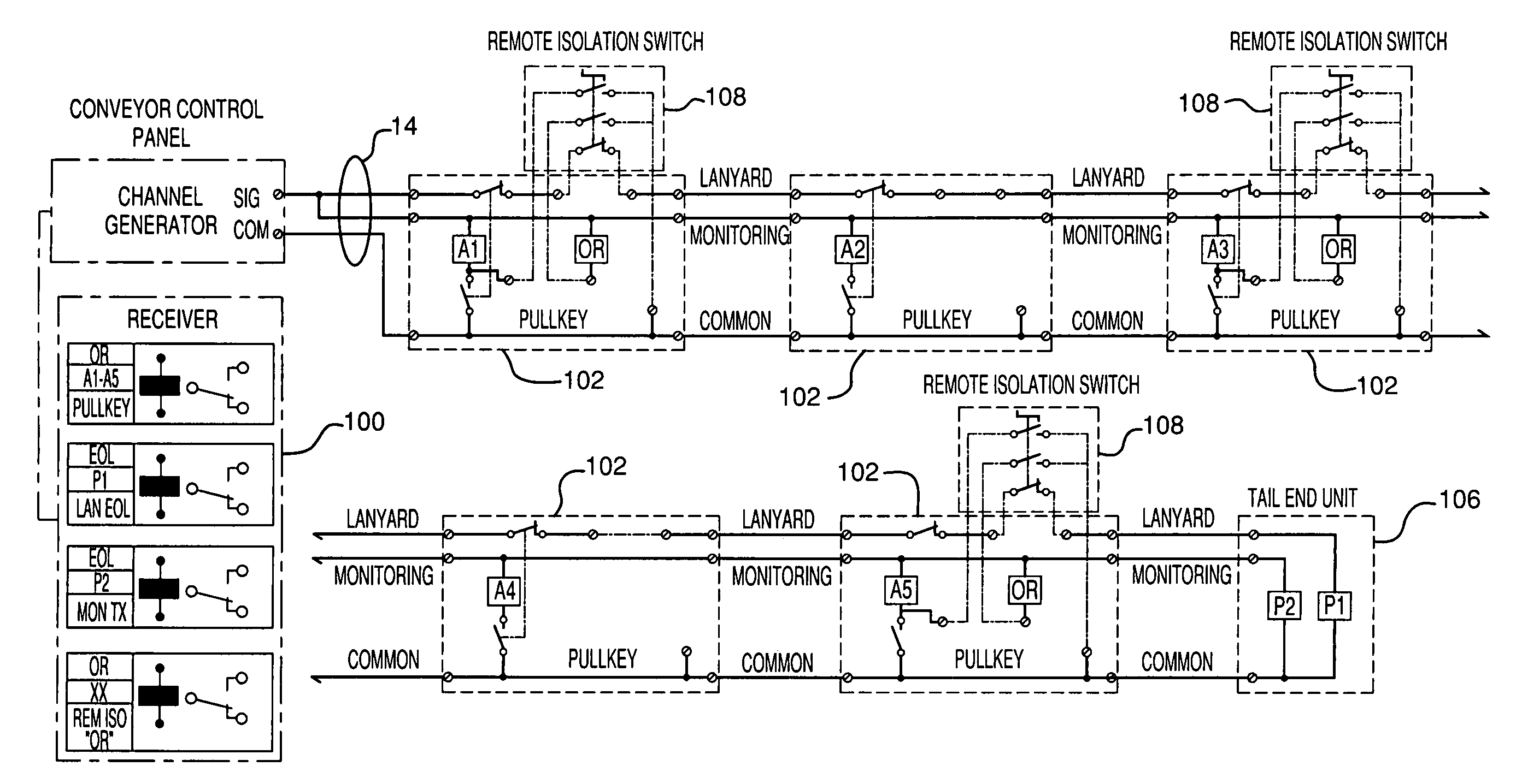
[0036]Referring now to the drawings, wherein like reference numerals designate identical or corresponding parts throughout the several views, exemplary embodiments of the present invention are shown in schematic detail.

[0037]Referring to FIGS. 2, 3A and 3B, an implementation of a field bus that provides power and signaling in systems and methods according to exemplary embodiments of the present invention, is illustrated with reference to plots of a pulse train and individual channel pulses for inbound and outbound communication.

[0038]In an exemplary implementation of the present invention, a conveyor monitoring system uses a two or three wire field bus system that provides both power and signaling on the same network. The system network is capable of extending to distances greater than 10,000 m with up to 128 transmission devices attached. The basis of data transmission along the field bus twisted pair or triplet network is that of pulse-width-modulation for outbound communications ...


PUM


Abstract

Lockout and monitoring system with SIL3 safety rating and method for lockout and monitoring of conveyor or any distributed plant are provided where pulse width modulation and amplitude modulation are used for communication between field devices (such as remote isolation switches deployed at various locations of a conveyor belt) and a central controller, and for indication of the device location. A fail safe redundant switching system for control circuit with additional transmitter and receiver modules are provided in combination with the means for accurate indication of switch location to achieve SIL 3 rating. The ability to provide control (analogue and digital outputs) for a distributed plant, for example along the length of a conveyor, is advantageously achieved, particularly when the control outputs are line powered by means of a field bus system that provides both power and signaling on the same network.

Description

BACKGROUND OF THE INVENTION[0001]1. Field of the Invention[0002]The present invention is directed in general to conveyor systems or any distributed plant, and in particular to monitoring and safety devices associated with such systems.[0003]2. Discussion of the Background[0004]Conveyor lockout and monitoring systems are generally employed in mining and manufacturing operations for overland and underground conveyor belts.[0005]In the operation of any conveyor installation, there is a need for a method of stopping the conveyor in an emergency situation and safely remote isolating the conveyor for maintenance purposes. Several methods exist today to accomplish the basic emergency stop and isolation functions but these have no location information. Existing systems include:[0006]Simple series connection of mushroom or lanyard operated emergency stop switches to the conveyor motor control circuit. This type of system is subject to critical safety issues when simple electrical cable fault...

Claims


Application Information

Patent Timeline
Patent Type & Authority Patents(United States)
IPC IPC(8): G05B11/01G05B9/02
CPCG05B19/418Y02P90/02
Inventor COLE, SIMON M.BROWN, PHILIP G.GILMOUR, RODERICK
Owner HUBBELL INC
Why Eureka
Try Eureka