
Heat-resistant cast iron and exhaust equipment member formed thereby

a technology of exhaust equipment and cast iron, which is applied in the direction of engine components, mechanical equipment, machines/engines, etc., can solve the problems that oxidation cannot be suppressed fully, and achieve excellent oxidation resistance and thermal crack resistance, and low cost

Active Publication Date: 2010-09-14
HITACHI METALS LTD
View PDF15 Cites 7 Cited by
  • Summary
  • Abstract
  • Description
  • Claims
  • Application Information

AI Technical Summary

Benefits of technology

[0021]Accordingly, an object of the present invention is to provide heat-resistant cast iron having excellent oxidation resistance and thermal crack resistance, from which, for instance, highly heat-resistant exhaust equipment members for automobile engines can be produced at low costs.DISCLOSURE OF THE INVENTION
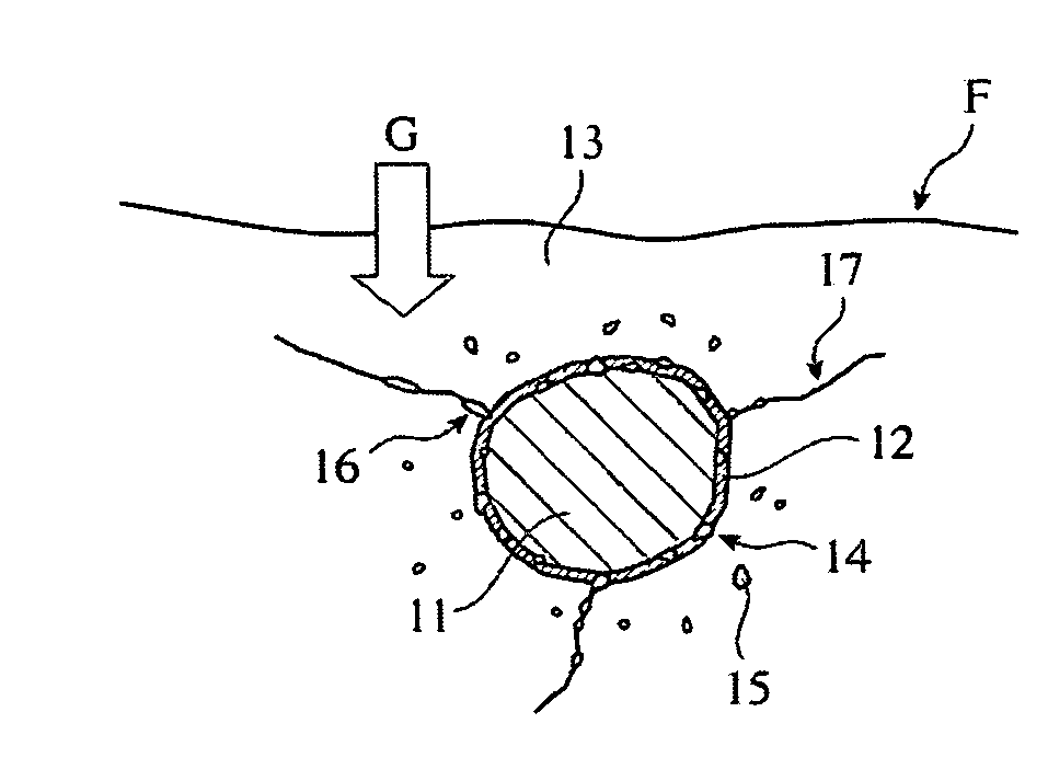
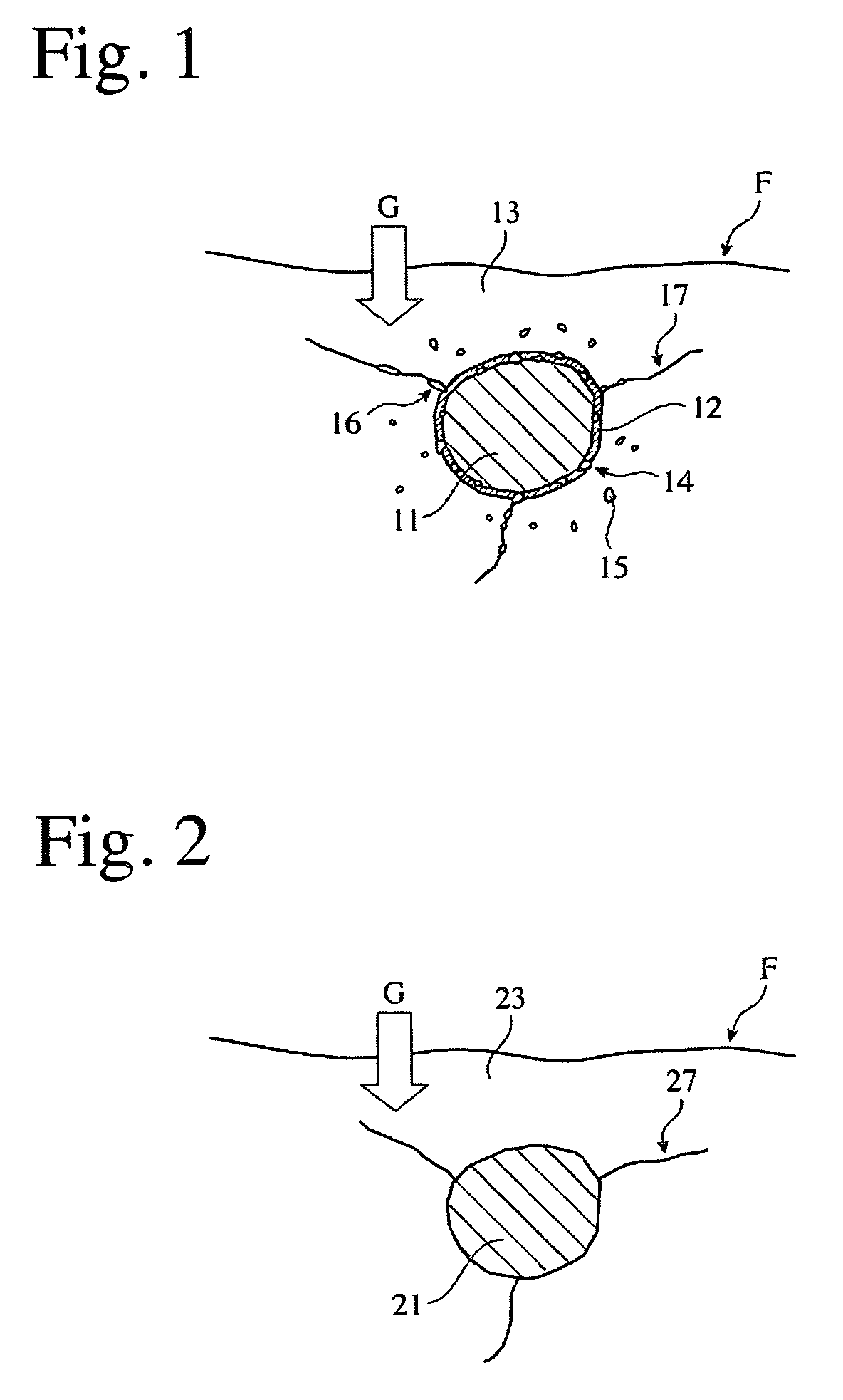
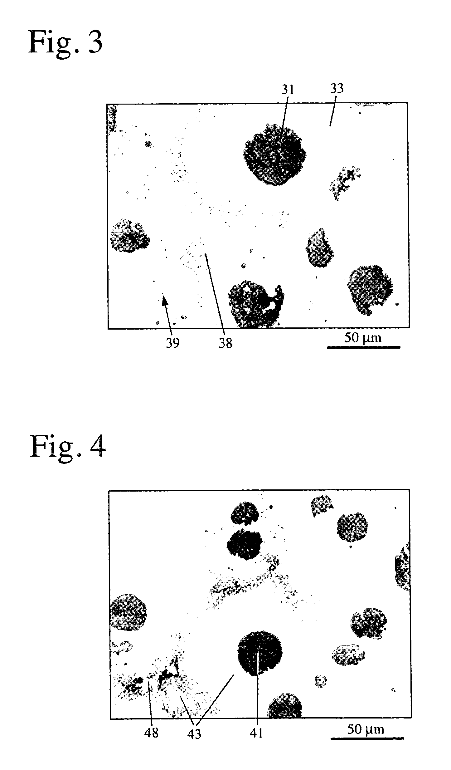
[0023]To improve the oxidation resistance and thermal crack resistance of cast iron, it is necessary to suppress the oxidation of graphite particles and their surrounding matrix regions, which tends to cause internal oxidation and cracking. However, such oxidation cannot necessarily be suppressed fully only by improvement in the shape and distribution of graphite particles as proposed above to suppress the internal oxidation of flake graphite cast iron. This is because when oxidizing gases intrude into the cast iron along the graphite particles, oxidation occurs in the graphite particles and their surrounding matrix regions. As a result intense research, the inventors have found that to prevent graphite particles and their surrounding matrix regions from being oxidized, it is effective to form intermediate layers, in which W and Si are concentrated, in boundaries of graphite particles and the matrix.
[0025]The graphite-containing, heat-resistant cast iron of the present invention comprises predetermined amounts of W and Si, and has intermediate layers, in which W and Si are concentrated, in boundary regions of graphite with a matrix. The intermediate layers act as protective layers (barriers) to suppress the intrusion of oxidizing gases into the graphite from outside and the diffusion of C from the graphite particles, thereby preventing the oxidation of the graphite particles and their surrounding matrix regions, and thus improving the oxidation resistance and thermal crack resistance of the heat-resistant cast iron.
[0029]The heat-resistant cast iron of the present invention comprises graphite particles and W, with W-containing carbide substantially in boundaries of graphite particles and the matrix. The W-containing carbide existing substantially in boundaries of graphite particles and the matrix suppress the intrusion of oxidizing gases from outside and the diffusion of C from the graphite particles, resulting in improved oxidation resistance. Because the W-containing carbide is also formed in grain boundaries in contact with the graphite particles, in which the diffusion of oxidizing gases and C appears to occur predominantly, the diffusion of oxidizing gases and C are effectively prevented.

Problems solved by technology

However, such oxidation cannot necessarily be suppressed fully only by improvement in the shape and distribution of graphite particles as proposed above to suppress the internal oxidation of flake graphite cast iron.

Method used


Image

  • Heat-resistant cast iron and exhaust equipment member formed thereby
  • Heat-resistant cast iron and exhaust equipment member formed thereby
  • Heat-resistant cast iron and exhaust equipment member formed thereby

Examples


examples 1-74

, COMPARATIVE EXAMPLES 1-16, AND CONVENTIONAL EXAMPLES 1-6

[0134]Each cast iron having a chemical composition (% by weight) shown in Table 1 was melted in an SiO2-lined, 100-kg, high-frequency furnace in the air, tapped from the furnace at 1450° C. or higher, and spheroidized by a sandwiching method using commercially available Fe—Si—Mg. Immediately thereafter, it was poured at 1300° C. or higher into a Y-block mold. After shake-out, each sample was shot-blasted, and annealed for ferritization by keeping it at a temperature of 600-940° C. as shown in Table 2 for 3 hours, and then cooling it in the furnace. Incidentally, no heat treatment was conducted on the samples of Example 9, Comparative Examples 1 and 9, and Conventional Examples 1, 2 and 4, and annealing for ferritization was conducted not by furnace-cooling but by air-cooling in the sample of Comparative Example 2. The samples of Conventional Examples 5 and 6 were spheroidized by a sandwiching method using commercially availab...

example 75

[0209]The exhaust manifold 151 schematically shown in FIG. 17 was formed from the heat-resistant cast iron of Example 9, and machined in an as-cast state. The resultant exhaust manifold 151 was free from casting defects such as shrinkage cavities, misrun, gas defects, etc., and did not suffer insufficient cutting, etc. at all when machined. In FIG. 17, 151a denotes flanges, 151b denotes branched tubes, and 151c denotes a convergence portion.

[0210]The exhaust manifold 151 of Example 75 was assembled to an exhaust simulator of a high-performance, 2000-cc, series-four-cylinder gasoline engine, to conduct a durability test to examine a life until cracking occurred and how the cracking occurred. The test condition was the repetition of a heating / cooling cycle comprising 10-minute heating and 10-minute cooling, to count the number of cycles until cracks penetrating the exhaust manifold 151 are generated. The exhaust gas temperature at a full load in the durability test was 920° C. at the ...

example 76

[0212]An exhaust manifold 151 was formed by the heat-resistant cast iron of Example 8 in the same manner as in Example 75 except for conducting annealing for ferritization by keeping it at 900° C. for 3 hours and then cooling it in a furnace. The resultant exhaust manifold 151 was free from casting defects, troubles such as heat-treatment deformation, and troubles during machining, etc. The exhaust manifold 151 of Example 76 was assembled to the exhaust simulator to conduct a durability test under the same condition as in Example 75. The surface temperature of the exhaust manifold 151 was the same as in Example 75. The durability test revealed that extremely small cracks were generated in the exhaust manifold 151 of Example 76 by 952 cycles substantially to the same degree and in the same portions as in Example 75. However, no cracks were generated in the convergence portion, through which a high-temperature exhaust gas passed, with substantially no oxidation occurring in the entire...


PUM

PropertyMeasurementUnit
weight ratioaaaaaaaaaa
temperatureaaaaaaaaaa

Abstract

A graphite-containing, heat-resistant cast iron for exhaust equipment members used at temperatures exceeding 800° C., comprising 3.5-5.6% of Si and 1.2-15% of W on a weight basis, and having intermediate layers, in which W and Si are concentrated, in the boundaries of graphite particles and a matrix. An exhaust equipment member formed by this heat-resistant cast iron has an AC1 transformation point is 840° C. or higher when measured from 30° C. at a temperature-elevating speed of 3° C. / minute, and a thermal cracking life of 780 cycles or more in a thermal fatigue test, in which heating and cooling are conducted under the conditions of an upper-limit temperature of 840° C., a temperature amplitude of 690° C. and a constraint ratio of 0.25.

Description

FIELD OF THE INVENTION[0001]The present invention relates to a heat-resistant cast iron having high oxidation resistance and thermal crack resistance, particularly to a heat-resistant cast iron suitable for exhaust equipment members for automobile engines, such as exhaust manifolds, turbocharger housings, catalyst cases, etc.BACKGROUND OF THE INVENTION[0002]Exhaust equipment members for automobile engines, such as exhaust manifolds, turbocharger housings, catalyst cases, exhaust manifolds integral with turbocharger housings, exhaust manifolds integral with catalyst cases, exhaust outlets, etc. are required to have improved heat resistance such as oxidation resistance and thermal crack resistance as well as high durability and long life, because they are used in such severe conditions as repeatedly exposed to high-temperature exhaust gases from engines with direct exposure to sulfur oxides, nitrogen oxides, etc. in the exhaust gas. The exhaust equipment members have conventionally be...

Claims


Application Information

Patent Timeline
Patent Type & Authority Patents(United States)
IPC IPC(8): C22C37/00C22C37/04F01N13/16
CPCC21D5/00C22C33/08F01N13/16C22C37/10C22C37/04C22C37/00
Inventor IGARASHI, YOSHIOENDO, SEIICHIMIYAKE, MASAHIROKAWATA, TSUNEHIRO
Owner HITACHI METALS LTD
Learn More