ROF link system for supporting various services

a technology of link system and service, applied in the field of radio over fiber link system for supporting various services, can solve the problems of difficult to separate signals, low intensity of uplink signal input through the antenna, and inefficient construction of remote antenna link every type of servi

Inactive Publication Date: 2010-09-14
SAMSUNG ELECTRONICS CO LTD
View PDF1 Cites 7 Cited by
  • Summary
  • Abstract
  • Description
  • Claims
  • Application Information

AI Technical Summary

Benefits of technology

[0016]Accordingly, the present invention has been made to solve the above-mentioned problems occurring in the prior art and provides additional advantages, by providing a radio-over-fiber (ROF) link system for supporting various services, which can prevent a TDD downward signal from exerting an influence upon upward signals by separating the TDD downward signal from an FDD upward signal in a remote access unit (RAU), and can transmit broadcasting signals together with TDD and FDD downward signals.

Problems solved by technology

In an environment in which various wireless services for voice, broadcasting, data, etc., are provided, it is inefficient to construct a remote antenna link every type of service.
Since the TDD system discriminates between uplink and downlink based on time bands and the FDD system discriminates between uplink and downlink based on frequency bands, it is difficult to separate a signal, to which TDD and FDD signals have been multiplexed, into uplink and downlink signals by using a switch or a filter.
Generally, since large signal loss occurs in the air environment, the intensity of an uplink signal input through the antenna is very low.
Therefore, the downlink signal output through the third port of the circulator has a relatively higher intensity than that of a received uplink signal, thereby saturating the amplifier for uplink, so that a downlink performance may deteriorate.
However, even in this case, it is impossible to reduce the intensity of a TDD downlink signal flowing into the uplink path, so that such a problem exerts a negative effect upon both uplinks of TDD and FDD systems.
A downlink signal flowing into an uplink path in an RF front-end device using a circulator may saturate the low-noise amplifier and / or the electric-optical converter or may cause operation of these devices with a lower current than an operational threshold current, thereby considerably deteriorating the uplink performance.
According to the conventional system as shown in FIG. 2, it is possible to prevent a TDD downward signal from exerting an influence upon an upward signal, but it has problems in that it is necessary to generate a separate control signal and to allocate a separate channel to transmit the control signal.

Method used


Image

  • ROF link system for supporting various services
  • ROF link system for supporting various services
  • ROF link system for supporting various services

Examples


first embodiment

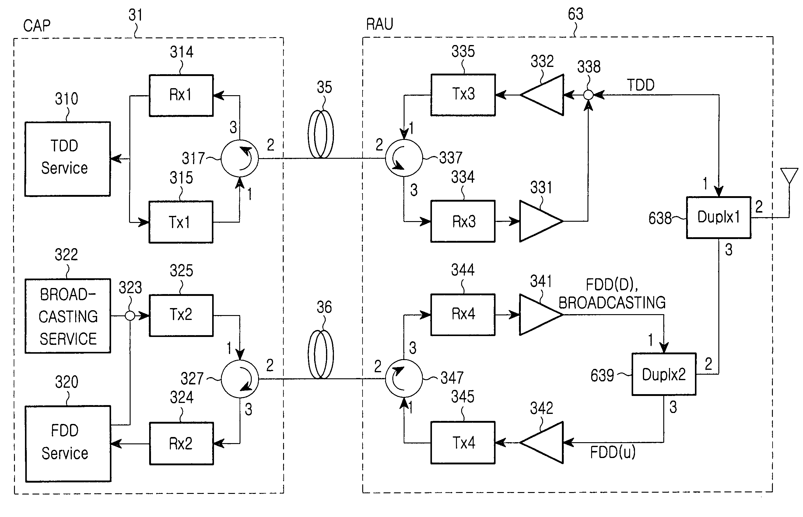
[0038]The operation of the system according to the present invention will now be described with reference to FIGS. 3, 4A and 4B. First, in the RAU 63 including the RF front-end device, a TDD downward signal transmitted from the CAP 31 is input to the third optical receiver 334 though the third optical circulator 337, is photo-electrically converted, is amplified through the first downward amplifier 331, and is then emitted through the antenna by way of the first duplexer 638. Also, an FDD downward signal and a broadcasting signal are input to the fourth optical receiver 344 through the fourth optical circulator 347, are photo-electrically converted, are amplified through the second downward amplifier 341, and are then emitted through the antenna by way of the second and first duplexers 639 and 638.

[0039]A TDD upward signal, which has been received through the antenna, passes through the first duplexer 638 and first upward amplifier 332, is converted into an optical signal by the thi...

third embodiment

[0051]T he operation of the RAU 33 in the system according to the present invention will now be described with reference to FIGS. 6, 7A and 7C. A TIDD downward signal transmitted from the CAP 31 is input to the third optical receiver 334 through the third optical circulator 337, is photo-electrically converted, is amplified through the first downward amplifier 331, and is then emitted through the first antenna by way of the first duplexer 3389. Also, the FDD downward signal and broadcasting signal are input to the fourth optical receiver 344 through the fourth optical circulator 347, are photo-electrically converted, are amplified through the second downward amplifier 341, and are then separated into the FDD downward signal and broadcasting signal by the diplexer 348. Then, the FDD downward signal are emitted through the second antenna by way of the second duplexer 349 and the and broadcasting signal emitted through the first antenna by way of first duplexer 338.

[0052]A TDD upward s...

fourth embodiment

[0055]According to such a construction, a TDD downward signal and FDD / broadcasting downward signals in the CAP 51 are wavelength-multiplexed by the first CWDM 510, and are then transmitted to the second CWDM 530. Then, the second CWDM 530 demultiplexes the multiplexed signal. Also, TDD and FDD upward signals, which have been output from the third and fourth optical circulators 337 and 347 in the RAU 53, are wavelength-multiplexed by the second CWDM 530, and are then transmitted to the first CWDM 510. Then, the first CWDM 510 demultiplexes the multiplexed signal. As the processing shown in FIG. 8, after de-multiplexing the received signals in CAP 51 and RU 53 are similar to that described with regard to FIG. 6, a detailed description of such processing need not be repeated for one skilled in the art to understand the principles of this fourth embodiment of the invention.

[0056]As described above, the ROF link system for supporting various services according to the present invention pr...


PUM


Abstract

Disclosed is a radio-over-fiber (ROF) system for supporting various services, the system comprising: a central access platform (CAP) for providing time division duplexing (TDD), frequency division duplexing (FDD), and broadcasting services, converting a TDD downward signal and FDD / broadcasting downward signals into optical signals, respectively, transmitting the converted optical signals to a remote access unit (RAU), converting a TDD upward signal and an FDD upward signal, which have been transmitted as optical signals from the RAU, into electric signals, respectively, and using an optical circulator in order to separate upward and downward signals from each other; and the RAU for converting the TDD downward signal and FDD / broadcasting downward signals transmitted from the CAP into electric signals, respectively, converting the TDD upward signal and FDD upward signal to be transmitted to the CAP into optical signals, respectively, and using an optical circulator in order to separate upward and downward signals from each other, wherein the RAU includes a plurality of signal filtering / separating / combining units, which wirelessly emit the TDD downward signal and FDD / broadcasting downward signals, having been converted into electric signals, through an antenna, and which separate wirelessly-received TDD upward signal and FDD upward signal from each other.

Description

CLAIM OF PRIORITY[0001]This application claims the benefit of the earlier filing date, pursuant to 35 U.S.C. 119(a), to that patent application entitled “ROF Link System For Supporting Various Services” filed in the Korean Intellectual Property Office on Dec. 22, 2005 and assigned Serial No. 2005-127761, the entire contents of which are incorporated herein by reference.BACKGROUND OF THE INVENTION[0002]1. Field of the Invention[0003]The present invention relates to a radio-over-fiber link system for supporting various services.[0004]2. Description of the Related Art[0005]With the diversification and rapid increase of information and communication services, it becomes necessary to provide very high speed wireless multimedia communication service through combination of the optical communication technology and the wireless communication technology. Accordingly, interest is being focused on a technology of applying a microwave to a very high-speed optical communication network, by combin...

Claims


Application Information

Patent Timeline
Patent Type & Authority Patents(United States)
IPC IPC(8): H04B10/00
CPCH04B10/25758H04H20/69H04H20/71H04W88/085H04W88/10H04B10/2575H04B10/25
Inventor LEE, HAN-LIMHWANG, SEONG-TAEKKIM, BYUNG-JIKLEE, GYU-WOONGKIM, HOONLEE, JAE-HOONKIM, YONG-GYOOKIM, SANG-HOKIM, SUNG-KEE
Owner SAMSUNG ELECTRONICS CO LTD
Why Eureka
Try Eureka