Method for selecting real-time service data transmission path

a real-time service and path selection technology, applied in the field of routing selection technique, can solve the problems of inability to reliably transmit critical services to be guaranteed in the prior network, large impact on real-time services, and unpredictable actual effects, so as to improve path selection efficiency and success ratio, facilitate implementation, maintain and manage, and ensure the effect of path establishmen

Active Publication Date: 2010-10-19
HUAWEI TECH CO LTD
View PDF28 Cites 23 Cited by
  • Summary
  • Abstract
  • Description
  • Claims
  • Application Information

AI Technical Summary

Benefits of technology

[0018]In view of this, a main object of the present invention is to provide a method for selecting a real-time service data transmission path, which can not only increase success ratio of routing, but also obtain an optimal end-to-end route in a simple and flexible manner and guarantee reasonable resource allocation.
[0019]Another object of the present invention is to provide a method for selecting a real-time service data transmission path based on forward constraint and backward routing, which can increase success ratio of routing and guarantee reliable route establishment.
[0020]Still another object of the present invention is to provide a method for selecting a real-time service data transmission path based on hop-by-hop routing, which can increase success ratio of searching a next hop route by a bearer network resource manager and guarantee reliability of resource allocation.

Problems solved by technology

Since a real-time service is sensitive to some functions such as network transmission delay and delay jitter, when there are services like File Transfer Protocol (FTP) with high burst quality or Hyper Text Transfer Protocol (HTTP) with image files etc., real-time services will be greatly affected.
In addition, since multimedia services occupy a wide range of bandwidths, the critical services to be guaranteed cannot be transmitted reliably in the prior networks.
The Diff-Serv model guarantees QoS only by setting priorities, which makes actual effect unpredictable though the line utilization ratio is high.
In this scheme, because a bearer network resource manager acquires LSP information directly from a bearer network and it is required to reacquire and reselect corresponding LSP for each call, LSP information cannot be repeatedly used, which results in high routing load and low efficiency of a bearer network resource manager.
This technique scheme has disadvantages as follows, topology and management is very complicated because a bandwidth broker directly manages resources and configuration information of all routers in the area; a route table needs to be updated frequently because a bandwidth broker needs to record dynamic route information of the local area, which will lead to instable network reservation; the service route determined by a bandwidth broker according to dynamic route information of the local area is difficult to be identical with the actual forwarding route of the service stream.
However, if there are large amount of service requests with low priorities and small amount of service requests with high priorities, it will lead to network congestion upon services with low priorities and bandwidth idle upon services with high priorities, therefore this scheme is inflexible and low-effective in routing.
In addition, this Rich QoS scheme relates to a pretty complex bearer network with a large number of routers.
Meanwhile, QoS server and strategy server notify edge routers by using explicit route MPLS LSP establishment technique and a mode of establishing end-to-end LSP, resulting in poor expansibility and limited network scale.
Thus, this scheme is not applicable for end-to-end service requirements in a public network.
However, since each domain is singly managed by a certain bearer network resource manager, a bearer network resource manager cannot know LSP resource conditions in other domains managed by other bearer network resource managers, which will bring uncertain factors for route availability and thus affect service efficiency of network.
For instance, when a forward routing manner is adopted between a source bearer network resource manager and a destination bearer network resource manager, with reference to network structure shown in FIG. 5, intra-domain routes and inter-domain routes are sequentially selected from a source ER to a destination ER hop by hop, but this route selection manner is liable to lead to route selection failure.
If LSP11 or LSP13 is selected, the route selection from bearer network resource manager 1 to bearer network resource manager 2 will be failed, thus leading to failure of entire routing.
Therefore, in the above case, only adopting forward route selection manner cannot obtain reasonable resource allocation, and the main reason is that one bearer network resource manager does not know LSP resource utilization condition in those domains managed by other bearer network resource managers.
In addition, there may be some rule constraints for certain specified performance requirements and services in domains managed by certain bearer network resource managers, for example some specified streams are allowed to or forbidden to pass in a certain intra-domain LSP, which may also lead to route selection failure.
However, if simply replacing forward route selection with backward route selection, the above-mentioned problem is also inevitable.
Thus requirements of various services cannot be satisfied well.
In this case, while implementing intra-domain route selection, once information of a certain router is updated, for example when developing a new service or a service is updated, information of the bearer network resource manager on bearer control layer should also be updated, which may lead to instability of network reservation.
Meanwhile, bearer network resource manager needs to record dynamic route information in the local domain, which may result in a problem that routing table will be updated frequently.
In this case, network reservation will be instable, and it is also difficult to guarantee the determined service route to be the same as the actual forwarding route of the service stream.

Method used


Image

  • Method for selecting real-time service data transmission path
  • Method for selecting real-time service data transmission path
  • Method for selecting real-time service data transmission path

Examples


first embodiment

The First Embodiment

Forward Constraint and Backward Routing

[0099]Main idea of this routing method is as follows. Each bearer network resource manager, including a source bearer network resource manager, selects a next hop bearer network resource manager according to destination address in a request message and network topology structure after detecting itself is not a destination bearer network resource manager according to the received connection resource request message, namely after detecting the service stream in this request message should not be transmitted to external networks via any ER inside management domain of this bearer network resource manager, and then sends the connection resource request message to the next hop bearer network resource manager, and reserves inter-domain route resources between itself and the next hop bearer network resource manager. If detecting that itself is the destination bearer network resource manager according to the received connection resou...

second embodiment

The Second Embodiment

Hop-by-Hop Routing Manner

[0125]The present routing scheme provides a method of hop-by-hop routing in a bearer network, its key idea is: under the condition that each bearer network resource manager in a bearer control layer only knows the topology structure of its own management domain, or under the condition that each CN only knows its adjacent CNs, the bearer network resource manager or the CN will only select and determine a next hop bearer network resource manager or a next hop CN.

[0126]FIG. 8 is a flowchart of signaling route path establishment in a bearer control layer by utilizing the hop-by-hop routing method of the current embodiment.

[0127]In step 801, a source bearer network resource manager receives a connection resource request message from a CA, the request message including connection information, QoS parameters, service type etc. Here, the connection information includes session ID, IP address or domain name of a calling party, IP address or domai...

third embodiment

The Third Embodiment

Static Routing Manner

[0158]The core idea of the present embodiment is as follows. Route path information is pre-configured either in a bearer network resource manager statically or by utilizing a dedicated database. A bearer network resource manager acquires the configured route path information when being activated, and selects a proper route path from the pre-configured route path information after receiving a connection resource request or a connection resource response, so that establishment and selection of route path are completely separated. Here, the configured route path information can be placed in a route table with entry routers and exit routers as column items and row items respectively. The table can be a route table indicating relationship between ER and BR, or be one indicating relationship between BRs.

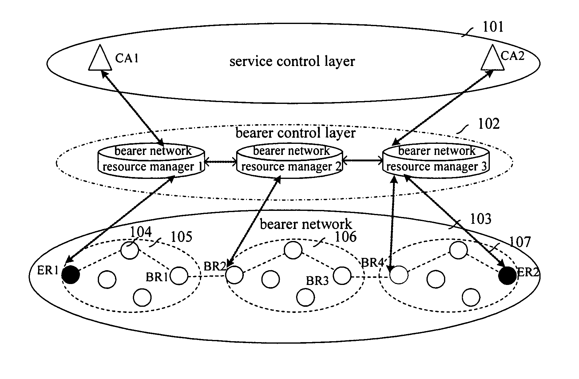
[0159]In the present embodiment, data transmission is implemented via a network based on the Diff-serv model shown in FIG. 1. The route in the bear...


PUM


Abstract

The present invention discloses a method for selecting a real-time service data transmission path, comprising establishing an independent bearer control layer comprising more than one bearer network resource manager between a service control layer and a bearer network. The method further comprises: after a source bearer network resource manager which is connected to the service control layer receives a connection request for a real-time service, orderly selecting and determining, from the source bearer network resource manager towards a destination bearer network resource manager, an intra-domain route path for the real-time service in a management domain corresponding to each bearer network resource manager, and an inter-domain route path between adjacent management domains corresponding to adjacent bearer network resource managers. In addition, the present invention discloses six methods for selecting a real-time service data transmission path based on different strategies. The methods according to the present invention can increase success ratio of routing, and can obtain an optimal route in simple and flexible manners, thus can guarantee reasonable allocation of resources.

Description

CROSS-REFERENCE TO RELATED APPLICATIONS[0001]The present application is a National Phase Patent Application of International Application Number PCT / CN2004 / 001015, filed on Sep. 2, 2004, which claims priority from Chinese Patent Application No. 03156163.2 filed on Sep. 2, 2003; Chinese Patent Application No. 03156162.4 filed on Sep. 2, 2003; Chinese Patent Application No. 03157640.0 filed on Sep. 2, 2003; Chinese Patent Application No. 03157639.7 filed on Sep. 2, 2003; Chinese Patent Application No. 03159179.5 filed on Sep. 10, 2003; Chinese Patent Application No. 03157145.X filed on Sep. 16, 2003; Chinese Patent Application No. 03157329.0 filed on Sep. 18, 2003; Chinese Patent Application No. 03126411.5 filed on Sep. 27, 2003; Chinese Publication No. 200310113001.9 filed on Dec. 24, 2003; and Chinese Publication No. 200410030941.6 filed on Apr. 1, 2004 the contents of which are incorporated herein by reference.FIELD OF THE TECHNOLOGY[0002]The present invention relates to routing sel...

Claims


Application Information

Patent Timeline
Patent Type & Authority Patents(United States)
IPC IPC(8): G06F15/16H04L12/28H04L12/56H04L45/50H04L45/74
CPCH04L45/02H04L45/04H04L45/302H04L45/3065H04L45/308H04L45/42H04L45/50H04L45/64H04L47/22H04L47/2408H04L47/2425
Inventor CHEN, YUEPENGFAN, LINGYUANWU, DENGCHAOXU, BOSUI, SHAOSHUAIHUANG, JIANZHONGQING, WU
Owner HUAWEI TECH CO LTD
Why Eureka
Try Eureka