Electrical power distribution system

a power distribution system and power distribution technology, applied in the direction of coupling contact member, coupling device connection, coupling contact member engagement/disengagement, etc., can solve the problem that most of the prior track or busway system is unsuitable for mission critical applications, and achieve the effect of reducing the chance of improper installation or excessive wear during repeated connection

Active Publication Date: 2010-10-26
POWER DISTRIBUTION
View PDF4 Cites 101 Cited by
  • Summary
  • Abstract
  • Description
  • Claims
  • Application Information

AI Technical Summary

Benefits of technology

[0013]Because of the contact-extending shaft-cam system used to connect power taps to the power track housing assembly of the preferred embodiment, the preferred power track housing assembly has the advantage that it does not require the plug-in p...

Problems solved by technology

However, most of the prior track or busway systems are unsuitable for mission critical applications because of the lack of adequate protection and monitoring features, and as a result t...

Method used


Image

  • Electrical power distribution system
  • Electrical power distribution system
  • Electrical power distribution system

Examples


Embodiment Construction

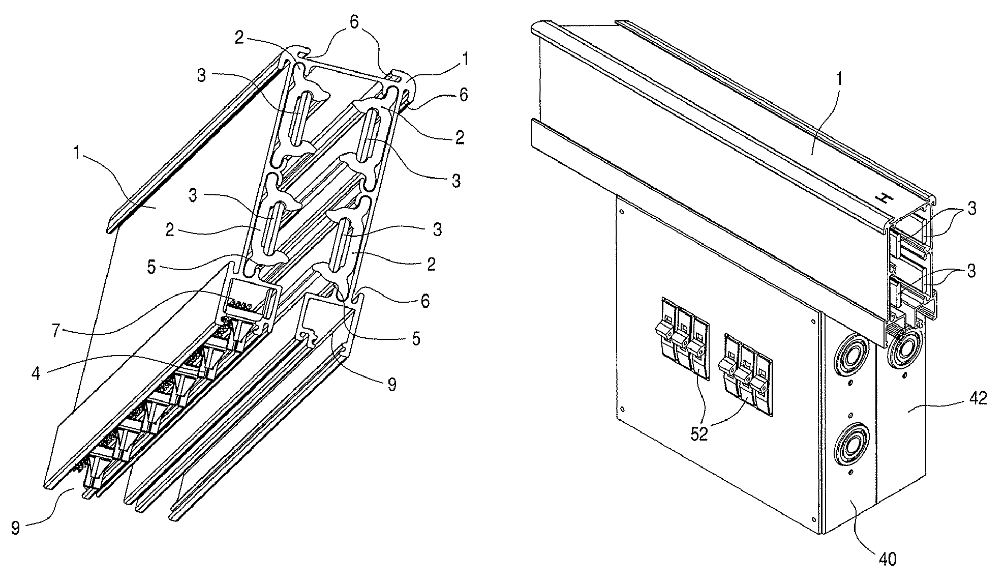
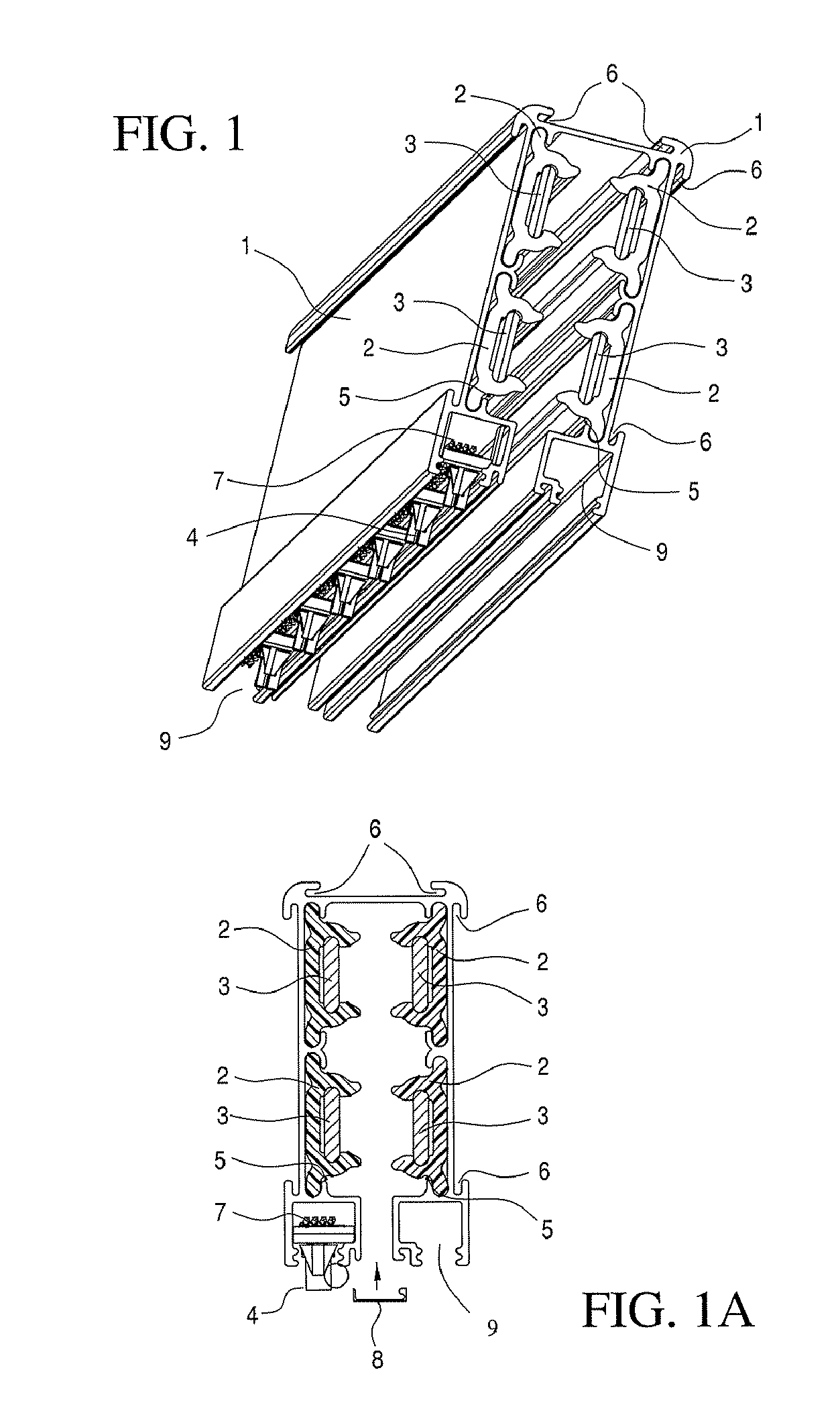
[0036]FIGS. 1 and 1a illustrate a power track housing assembly with isolated high current conductors or bus bars 3 according to a preferred embodiment of the invention. The power track housing assembly of FIG. 1 is made up of four major components: a housing or enclosure 1; insulators 2; the high current conductors or bus bars 3; and communications components including signal connectors 4 and cable 7. Housing or enclosure 1 may include grooved runways 6 extending along the top and sides of the housing assembly for mounting or securing EMI shielding in the form of flat plates (not shown) made of a magnetically conductive material such as Mu metal, and / or mounting plates (not shown) made of the a magnetically conductive material for mounting the runway to a wall or ceiling.

[0037]In addition, the housing 1 of the power track housing assembly may be provided with sub-cavities 9, and / or compartments, passages, grooves, recesses, or the like to accommodate the insulators and / or sign...


PUM


Abstract

An electrical power distribution system that can provide power to load equipment at any point along its length includes two main components: a power track housing assembly with current carrying conductors that can be mounted to the wall, ceiling or under the floor, and a plug-in power tap. The power track housing assembly includes a housing, insulators, and two or multiple conductors. In order to increase the housing assembly length, the housing assembly is preferably arranged such that multiple housing assemblies can be spliced together using cam operated splicing assemblies that form straight, “90 degree” and/or “T” splices to configure the system to match the equipment arrangement, and that allow all conductors in respective housing assemblies to be connected to each other simultaneously. The plug-in power taps also employ a system such as a shaft-cam mechanism that allows the assemblies to be electrically connected to all phase conductors within the power track housing assembly simultaneously. In addition, the power taps may include circuit breakers or other protective devices, and/or other sub-modules.

Description

BACKGROUND OF THE INVENTION[0001]1. Field of the Invention[0002]This invention relates to a system for distributing electrical power from a junction box to electrical devices via a busway or track, to which distribution sub-assemblies or power taps may be removably connected without shutting down the power supply. The busway or track includes multiple conductors to provide DC power, or single or multiple phase AC power, with multiple track sections or housing assemblies being joined together by unique cam operated splicing assemblies, and the power taps also being connected to the track sections or housing assemblies by a contact extending mechanism or device, such as a cam, that does not require the power tap mechanical structure to be rotated once installed in the power track housing assembly in order to make electrical connection to the track conductors.[0003]2. Description of Related Art[0004]The rigorous demands of mission critical data center sites require methods to quickly d...

Claims


Application Information

Patent Timeline
IPC IPC(8): H01R25/00
CPCH01R13/245H01R13/2457H02G3/105H02G3/0431H01R25/145H02G5/08
Inventor CARDOSO, ROBERTOCORTES, TIMOTHYHORTA, ENRIQUEJAUREGUI, MIGUELKAMMETER, JOHNKATZ, ALANSCHMID, KEITH
Owner POWER DISTRIBUTION
Why Eureka
Try Eureka