Manufacturing method of optical information recording medium

a manufacturing method and optical information technology, applied in the field of manufacturing optical information recording media, can solve the problems of disc out of focus colliding with the lens, damage to the surface of the transparent cover layer on the record/reproduction side, and inability to produce good recording and reproducing characteristics, and achieve high shrinkage percentage , the effect of efficiently controlling warpage to a small amoun

Active Publication Date: 2010-10-26
PANASONIC CORP
View PDF28 Cites 2 Cited by
  • Summary
  • Abstract
  • Description
  • Claims
  • Application Information

AI Technical Summary

Benefits of technology

[0019]When the material for the transparent cover layer is the radiation cure type resin, a warpage control layer may be formed on a principal surface on the opposite side of a principal surface which is formed with the transparent cover layer. In this case, the thickness of the warpage control layer and the shrinkage percentage of the material for the warpage control layer are preferably so selected as to provide the optical information recording medium with a warpage angle of 0.35 degrees or less. Under such conditions, the warpage angle can be controlled to 0.35 degrees or less by selecting the type of the warpage control layer and the formed thickness, even when the optical information recording medium formed with the transparent cover layer warps toward the transparent cover layer side. At a warpage angle of 0.35 degrees or less, good recording and reproducing characteristics can be obtained, even when the recording/reproducing apparatus has no warpage control function.
[0020]In the layer forming process, the material for the warpage control layer may have a cure shrinkage percentage that is higher than that of the radiation cure type resin for the transparent cover layer, and the warpage control layer may have a thickness that is smaller than that of the transparent cover layer. Such a material with a high shrinkage percentage for a thin warpage control layer can efficiently control warpage to a small amount, and therefore, the process can be per

Problems solved by technology

In addition, the distance between the lens and the disc (working distance) is so small that the disc out of focus can collide with the lens due to a change in disc warpage and defects such as scratches and dust on the disc surface.
In such a case, the surface of the transparent cover layer on the record/reproduction side can be damaged by a collision with the lens.
Such damage to the surface of the transparent cover layer can result in lo

Method used


Image

  • Manufacturing method of optical information recording medium
  • Manufacturing method of optical information recording medium
  • Manufacturing method of optical information recording medium

Examples


first embodiment

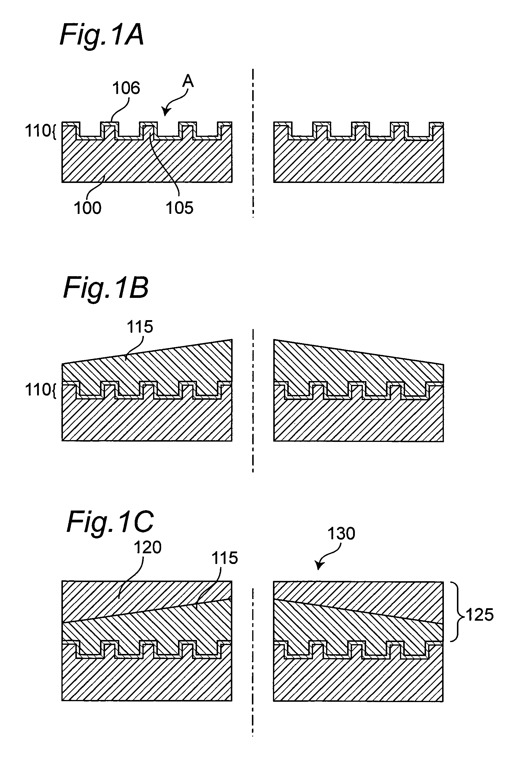
[0037]FIGS. 1A to 1C show an embodiment of a manufacturing method of the optical information recording medium according to the invention. Referring to FIG. 1A, first, a signal substrate 100 is prepared with a thickness of 1.1 mm. On a principal surface A of the signal substrate 100, concavities and convexities 105 are formed according to signals. The signal substrate 100 is made of plastic such as polycarbonate and acrylics and generally formed by an injection molding process. Alternatively, the 2P method may be performed to transfer the concavities and convexities 105 according to signals to the supporting substrate. A recording film 106 is formed on the concavity and convexity 105 according to signals to constitute a signal recording layer 110. The recording film 106 is a multilayer or monolayer film including at least one of a metal reflection film, a semiconductor film (for example, a phase change film such as a GeSbTe film), a dielectric film, and a pigment film. The method of ...

second embodiment

[0055]Here is a description of a manufacturing method of a recording medium having two signal recording layers formed in the direction of depth of the recording medium.

[0056]Referring to FIG. 6A, on a signal substrate 100, formed are a first signal recording layer 110 and a second signal recording layer 1000 formed under the first layer 110 via a separation layer 1001. The second signal recording layer 1000 includes concavity and convexity 1005 according to second signals and a second recording film 1006.

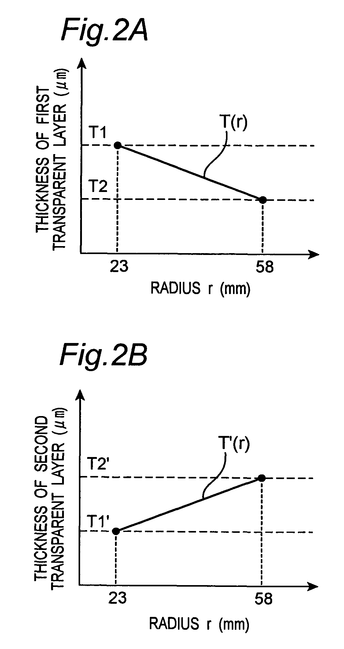
[0057]As shown in FIG. 6B, the first transparent layer 115 is formed on the first signal recording layer 110, and as shown in FIG. 6C, the second transparent layer 120 is formed thereon, by the method according to First Embodiment.

[0058]The thickness of the separation layer 1001 is determined depending on the numerical aperture of the lens used in recording and reproduction. The numerical aperture is determined depending on the recording densities of concavity and convexity 105 and ...

third embodiment

[0059]In this embodiment, provided is a method of forming the first transparent layer by screen printing. The second transparent layer is formed by the method of the above embodiment.

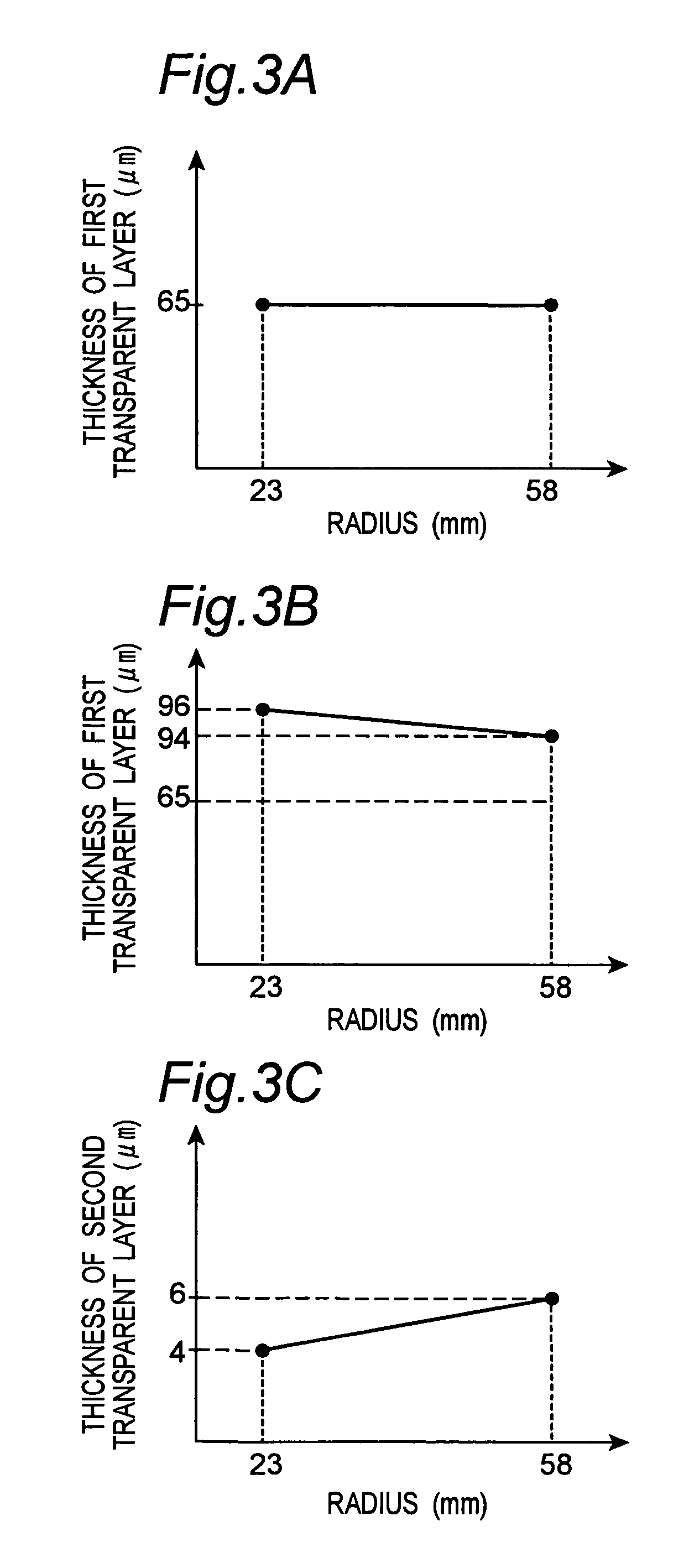
[0060]FIG. 7A shows a screen for use in forming the first transparent layer in this embodiment. Referring to the drawing, a screen 500 has a number of holes 510 each having a diameter D(R) depending on the distance (the diameter) R from the center and are concentrically arranged. FIG. 7B shows the relationship between the diameter D(R) of each hole and the diameter at which the hole is provided on the screen 500. It is preferred that the diameter D(R) of the hole decreases as the distance R increases, as shown in the drawing. The screen 500 is placed on the signal substrate 100, and according to the screen printing, the radiation cure type resin is allowed to pass through the screen 500 using a spatula or the like so that the first transparent layer 115 is provided in a similar form to that of the First...


PUM

PropertyMeasurementUnit
Lengthaaaaaaaaaa
Fractionaaaaaaaaaa
Angleaaaaaaaaaa

Abstract

A method of manufacturing an optical information recording medium to/from which signals can optically be recorded and reproduced. The recording medium includes a signal substrate (100), a signal recording layer (110), and a transparent cover layer (125) having a first transparent layer (115) and a second transparent layer (120), which is harder than the first transparent layer (115). Signals can be recorded and reproduced to and from the recording medium by a light transmitted to the signal recording layer through the transparent cover layer (125). The first transparent layer is formed so as to have a first predetermined distribution of thickness. The second transparent layer is formed so as to have a second predetermined distribution of thickness to make the total thickness of the transparent cover layer (125) uniform. The first transparent layer (115) may be made of a plurality of thin laminated transparent layers.

Description

BACKGROUND OF THE INVENTION[0001]1. Technical Field[0002]The invention relates to a method of manufacturing an optical information recording medium that includes a signal substrate, a signal recording layer formed on one of its principal surfaces and a transparent cover layer (for example, with a thickness of about 0.1 mm) formed on the signal recording layer, in which a focused light is transmitted through the cover layer in the process of signal recording and reproducing.[0003]2. Description of the Related Art[0004]Optical information recording media are known for their high-density recording and reproducing performance through a laser beam, and their use has become widespread. In recent years, for recording video information such as movies as well as sound information, digital versatile discs (DVDs) as large-capacity optical discs have been developed for market and have already become widespread. The high-density optical disc such as a DVD is used with a short wavelength laser be...

Claims


Application Information

Patent Timeline
IPC IPC(8): B05D5/06B05D3/06B05D3/12G11B7/24G11B7/24056G11B7/24094G11B7/24097G11B7/26
CPCG11B7/252G11B7/2542G11B7/266G11B7/2433G11B7/26
Inventor HAYASHI, KAZUHIROHISADA, KAZUYAABE, SHINYAHIGASHIMARU, KAZUHIROOHNO, EIJI
Owner PANASONIC CORP
Why Eureka
Try Eureka