Method and article of manufacture to generate IC test vector for synchronized physical probing

a technology of physical probing and test pattern, applied in the direction of electronic circuit testing, measurement devices, instruments, etc., can solve the problems of insufficient complete localization, inability to complete localization, and inability to directly mechanically probe on-die electrical signals, and achieve the effect of efficient introduction of care-bit patterns

Inactive Publication Date: 2010-10-26
CADENCE DESIGN SYST INC
View PDF7 Cites 3 Cited by
  • Summary
  • Abstract
  • Description
  • Claims
  • Application Information

AI Technical Summary

Benefits of technology

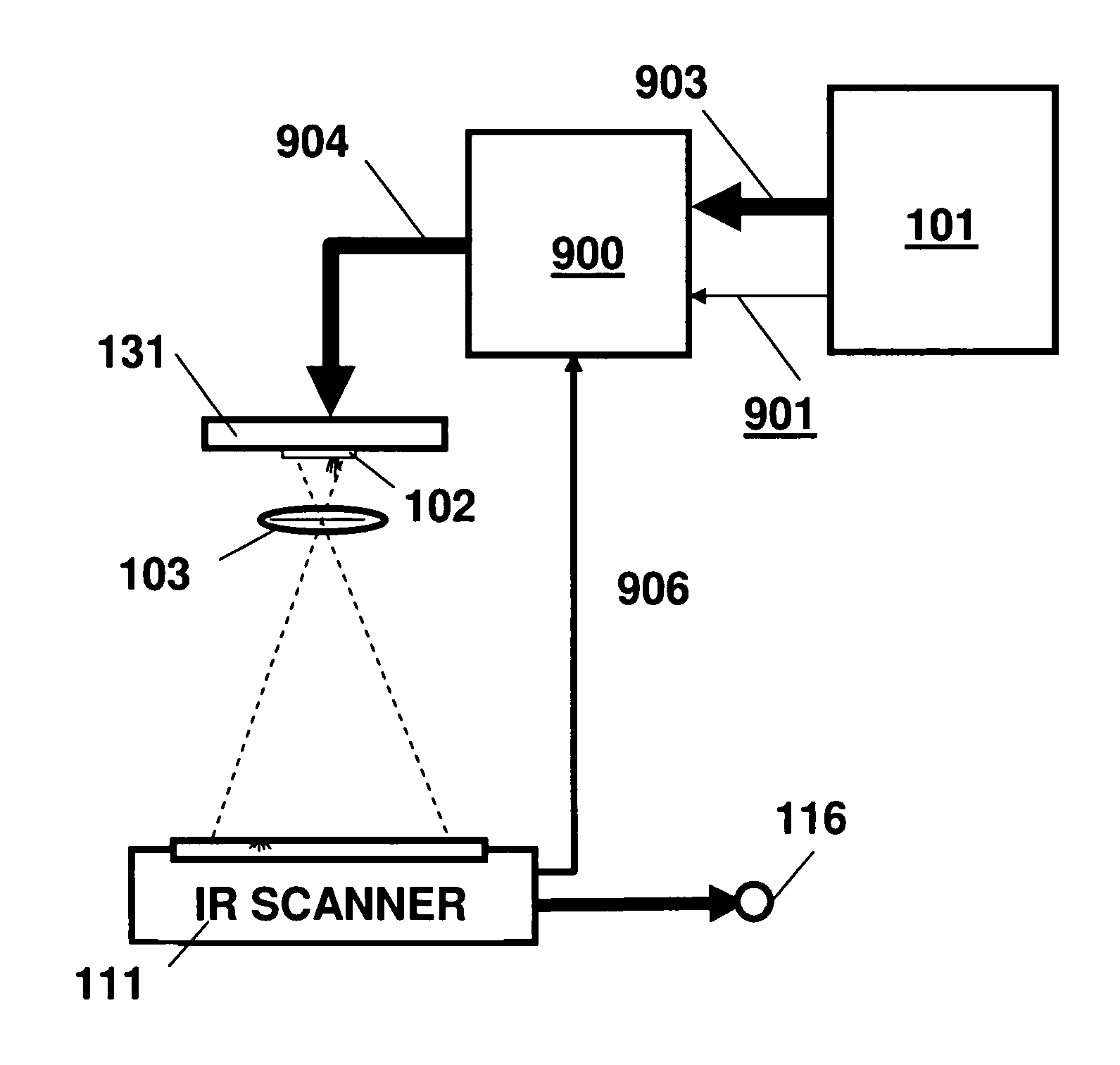
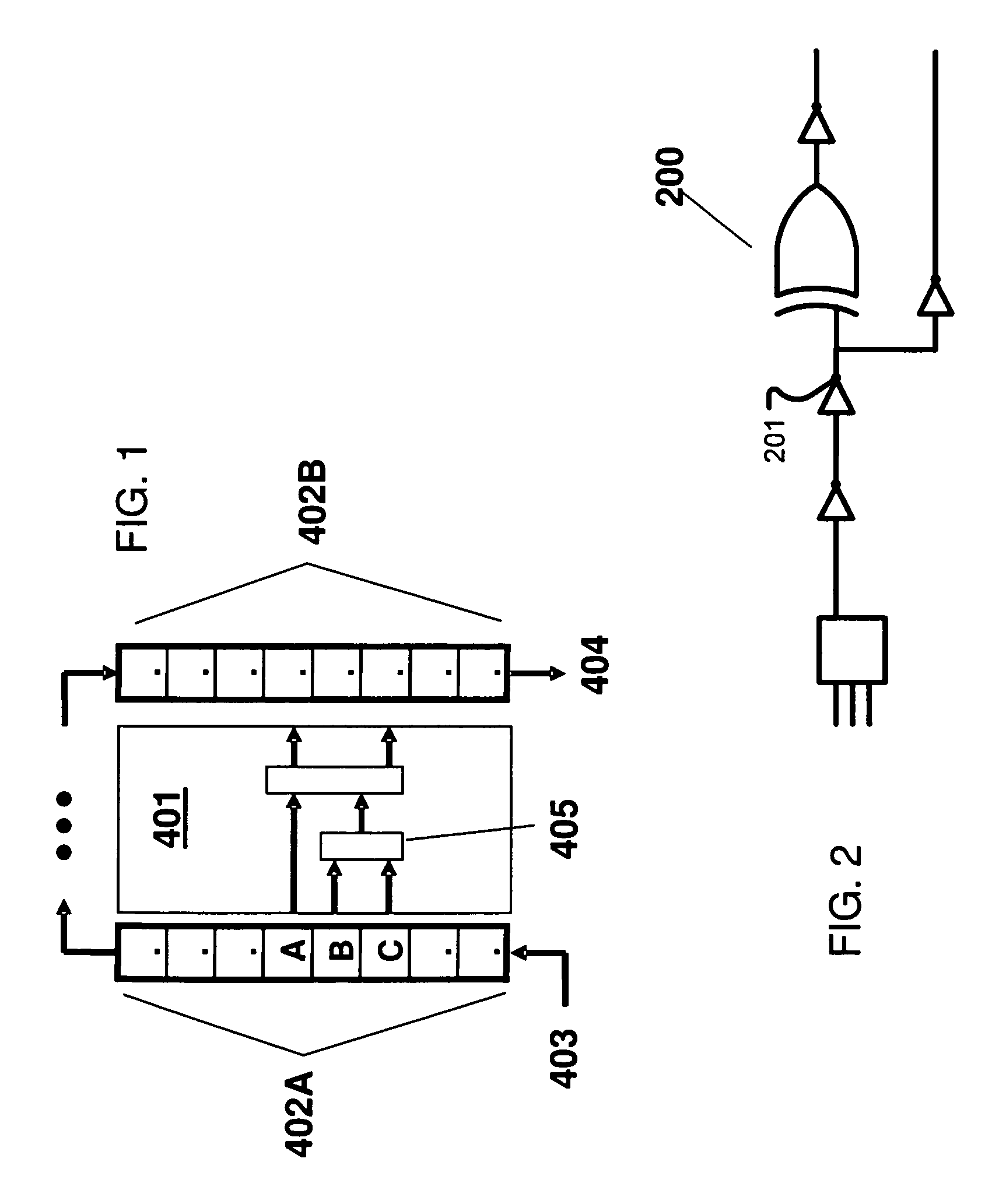
[0021]Embodiments of the present invention provide methods and apparatuses to efficiently introduce care-bit patterns at regular intervals into test vectors for IC testing. (“Care-bit patterns” are subsets of test vectors that exercise a sink latch of interest.) In further aspects, trigger signals also can be generated for use in synchronizing care-bit patterns with optical scanning at predictable times.

Problems solved by technology

As will be discussed below, electrical design-for-test (DFT) features such as a scan-based architecture will partially localize a problem but even when supplemented by diagnostic programs can be insufficient for complete localization.
The direct mechanical probing of on-die electrical signals, performed by placing very sharp probe tips on the nodes of interest, is sometimes impossibly difficult.
Often, such nodes are designed to drive capacitive loads on the IC of a few 10 s of fF and would be unacceptably loaded by the capacitance of electrical probes, thereby perturbing circuit functioning.
Node access can also present problems due to the large numbers of metal layers, and to the extremely small size of the nodes of interest on typical ICs.
Flip-chip packaging only compounds the access problem.
Electron-beam probing has historically been used, but it suffers from the same problems of access as do mechanical probes.
This is because, compared to electrical testing, physical testing tends to be more expensive in terms of testing time and testing equipment.
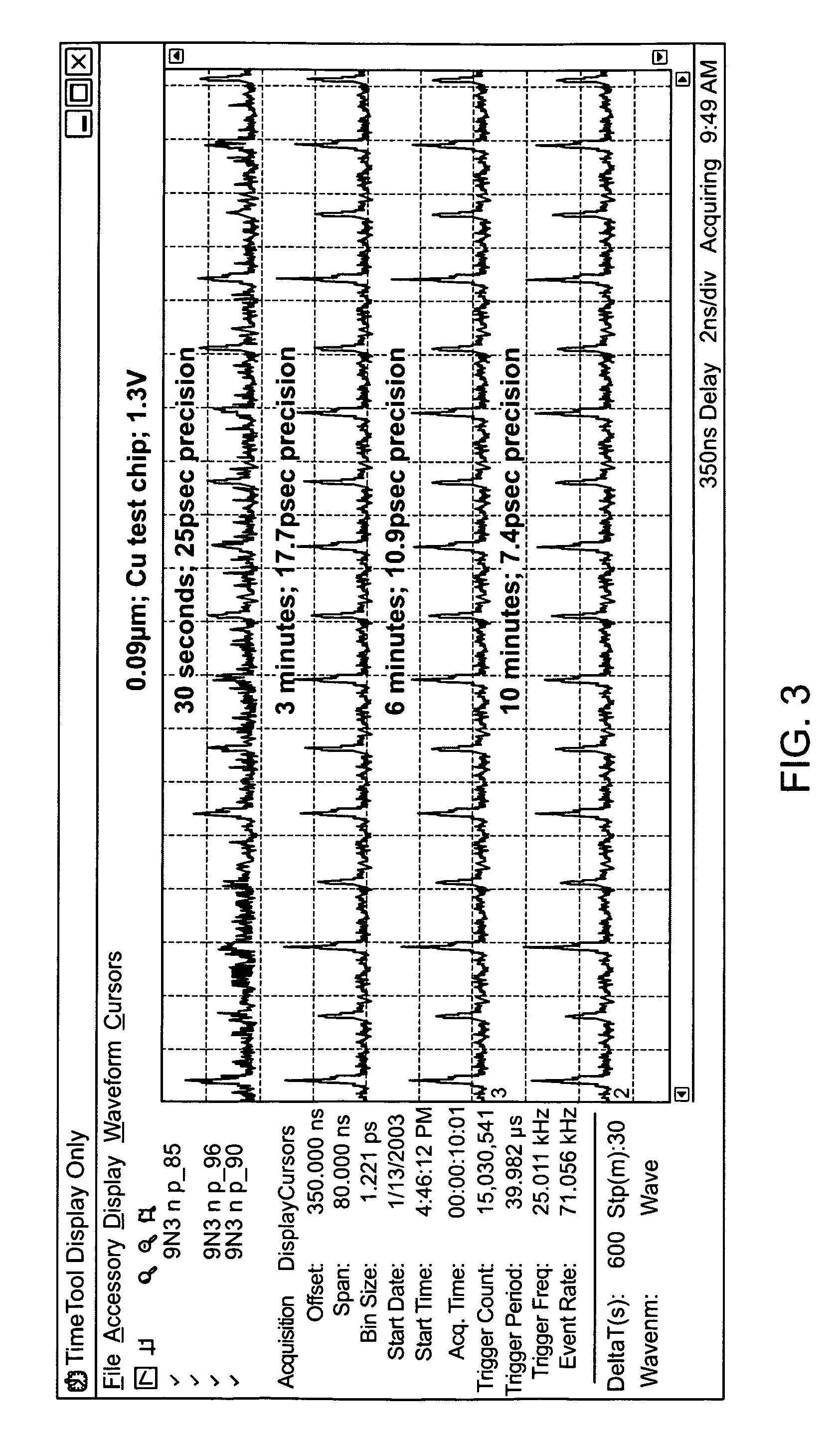
A performance-limiting factor in optical probing can be often the long averaging time required to accumulate enough test data.
A drawback of optical probing is that the signals acquired can be very weak.
A limitation, from a user's point of view, is the time it takes to acquire enough such “signal” to analyze functionality of the probed point, as this time usually limits the number of nodes that can be probed.
A discrepancy in test results and expected results indicates a performance fault for the digital circuit.
Left unchecked, this trend could result in unacceptably long acquisition times for testing.

Method used


Image

  • Method and article of manufacture to generate IC test vector for synchronized physical probing
  • Method and article of manufacture to generate IC test vector for synchronized physical probing
  • Method and article of manufacture to generate IC test vector for synchronized physical probing

Examples


Embodiment Construction

[0033]Unless defined otherwise, all technical and scientific terms used herein have a meaning consistent with a common understanding of those of ordinary skill in the art(s) to which this invention belongs.

[0034]In the following description, reference is made to the accompanying drawings which illustrate several embodiments of the present invention. It is understood that other embodiments may be utilized and mechanical, compositional, structural, electrical, and operational changes may be made without departing from the spirit and scope of the present disclosure. The following detailed description is not to be taken in a limiting sense, and the scope of the embodiments of the present invention is defined only by the claims of the issued patent.

[0035]Some portions of the detailed description that follows are presented in terms of procedures, steps, logic blocks, processing, and other symbolic representations of operations on data bits that can be performed on computer memory. A proce...


PUM


Abstract

Systems, methods, and computer readable media storing instructions for such methods relate to generating test vectors that can be used for exercising a particular area of interest in an integrated circuit. The test vectors generally include a non-overlapping repeating and / or predictable sequence of care bits (a care bit pattern) that can be used by a tester to cause the exercise of the area and collect emissions caused by exercising the area. Such emissions can be used for analysis and debugging of the circuit and / or a portion of it. Aspects can include providing a synchronization signal that can be used by a tester to allow sensor activation at appropriate times.

Description

CROSS REFERENCE TO RELATED APPLICATIONS[0001]This application is a continuation of U.S. patent application Ser. No. 11 / 877,516, filed on Oct. 23, 2007, now abandoned, which claims benefit under 35 U.S.C. §119(e) of U.S. Provisional Application No. 60 / 854,225, filed on Oct. 24, 2006, both applications are incorporated by reference in their entirety herein.TECHNICAL FIELD[0002]The present invention relates to the generation of test patterns (vectors) for IC operational testing, and more particularly to the efficient generation of test vectors that exercise circuit nodes and that can be synchronized with physical scanners for testing ICs.BACKGROUND ART[0003]For both IC debug and failure analysis, a goal is to understand a root cause of a failure. For debug analysis, the root-cause information can be provided to the design engineers who make appropriate changes to the mask set. In failure analysis, the data can be provided to the IC fabrication facility to effect changes directed toward...

Claims


Application Information

Patent Timeline
Patent Type & Authority Patents(United States)
IPC IPC(8): G01R31/302
CPCG01R31/31813
Inventor SWENTON, JOSEPHBARTENSTEIN, THOMASSCHOONOVER, RICHARDSLIWINSKI, DAVID
Owner CADENCE DESIGN SYST INC
Why Eureka
Try Eureka