
Analyzing instrument

a technology of analyzing instruments and instruments, applied in the field of analyzing instruments, can solve the problems of measurement errors, inability to keep the time taken for filling the capillary with blood (suction time) constant, and difficulty in proper measurement, and achieve the effect of accurately measuring the concentration of a target componen

Inactive Publication Date: 2010-11-02
ARKRAY INC
View PDF48 Cites 15 Cited by
  • Summary
  • Abstract
  • Description
  • Claims
  • Application Information

AI Technical Summary

Benefits of technology

[0012]An object of the present invention is to provide an analyzing instrument capable of properly supplying a sample liquid to a capillary and accurately measuring the concentration of a target component in the sample liquid.
[0019]Preferable examples of Vinylon include one whose degree of saponification is no less than 95% (preferably no less than 99%), one whose degree of acetalization is 30-40%, or one whose degree of saponification is no less than 95% (preferably no less than 99%) and whose degree of acetalization is 30-40%. Vinylon, which is a water-insoluble material, should preferably have a wettability of about 62N / m and a hygroscopicity of no less than 2%. By making at least part of the cover using such Vinylon, both of the dehumidification region and the high-wettability region can be provided by the Vinylon. For example, when a surface of the cover which becomes an inner surface of the capillary is made of Vinylon, the inner surface of the capillary (the inner surface of the cover) provides the high-wettability region and the dehumidification region throughout the length. With this structure, the speed of travel of the sample liquid along the inner surface of the cover can be reliably increased, whereby variations in the travel speed can be reduced. Further, the influences of moisture can be reliably reduced.
[0020]To ensure such effects, it is preferable to use a cover entirely made of Vinylon or a cover including a base at least one surface of which is covered with a Vinylon layer. Since such a cover has end portions made of Vinylon, a dehumidification region can be provided adjacent to the first and the second openings. When the cover is entirely made of Vinylon or opposite surfaces of the base of the cover are provided with Vinylon layers, it is possible to positively remove water existing around the capillary as well as water entering the capillary through the first and the second openings.
[0021]The wettability of Vinylon after it is heated at 80-140° C. for one second is no less than 57 mN / m. Therefore, even when the cover is fixed to the substrate using a hot-melt adhesive which melts at a temperature no more than 140° C., the high wettability of the inner surface of the capillary can be maintained. Therefore, it is possible to dispense with a hydrophobic double-sided tape, which causes the sample liquid to flow faster near the spacers than at other portions. Thus, it is possible to reduce variations in the liquid travel speed in the capillary while enhancing the measurement accuracy and the reproducibility.

Problems solved by technology

Such background current (noise) by the electrons due to water results in measurement errors.
Moreover, since the solubility of the reagent layer 97 changes in accordance with the hygroscopicity, the time taken for filling the capillary with blood (suction time) cannot be kept constant, which causes difficulty in proper measurement.
In this way, variation in the speed distribution of the blood flow hinders sufficient dissolving of the reagent layer 97 within a predetermined time, which may increase the measurement errors and deteriorate the reproducibility.
Further, in the biosensor 9, blood need be introduced after it is confirmed that the amount of blood needed for the measurement is extracted from the skin, because otherwise, the amount of blood introduced to the biosensor 9 may be insufficient or the time taken for filling the capillary with the blood after the starting of the blood introduction is not kept constant.
In this way, the use of the biosensor 9 for a blood glucose level measuring apparatus which is not provided with a lancet involves a large burden on the user.
Since the burden on the eyes is particularly large, the use is very difficult for a person who has weak eyesight due to the progress of diabetes, and the measurement accuracy is likely to be deteriorated.

Method used


Image

  • Analyzing instrument
  • Analyzing instrument
  • Analyzing instrument

Examples


example 1

[0099]In this example, the influences of hygroscopicity of the reagent layer on the suction speed were examined. The examination was performed using inventive biosensors which were similar in structure to the biosensor X2 shown in FIGS. 12 through 14, and comparative glucose sensors similar in structure to that shown in FIG. 23. The detailed structure of the biosensors is given in Table 1 below. As shown in Table 1, each of the inventive biosensors used for the examination had a Vinylon sheet attached to only one surface of a PET material, unlike the biosensor X2 shown in FIGS. 12 through 14. In each of the comparative biosensors, lecithin as a surface-active agent is applied to one surface of a PET material as a cover.

[0100]

TABLE 1(BIOSENSOR STRUCTURE)Capillary SizeTotalHeightWidthCover StructureLengthHWInventivePET of 100 μm6 mm120 μm1.2 mmBiosensorto one surfaceof which Vinylonsheet of 17 μmis attachedComparativePET of 100 μmBiosensorwith one surfacehydrophilicallytreated byapply...

example 2

[0103]In this example, the measurement reproducibility was examined. The examination of the measurement reproducibility was performed by comparing inventive biosensors with comparative biosensors with respect to change of responsive current with time. Specifically, while a standard solution was supplied to the reagent layer, a constant voltage of 200 mV was applied across the operative electrode and the counterpart electrode. The value of oxidation current flowing in this state was measured as the responsive current. The standard solution was prepared by dissolving glucose in physiological saline to provide a glucose concentration of 100 mg / dL while adjusting the blood cell concentration (Hct) to an intended value. The results for the inventive biosensors are given in FIGS. 18A, 19A and 20A, whereas the results for the comparative biosensors are given in FIGS. 18B, 19B and 20B. FIG. 18, FIG. 19 and FIG. 20 show the results when the Hct was 0%, 25% and 42%, respectively. The responsi...

example 3

[0107]In this example, the optimum capillary size was determined. The suction time was measured in the same manner as in Example 1 with respect to biosensors 1-12 including inventive and comparative biosensors which were the same in basic structure as those used in Example 1 but which had various capillary sizes. To evaluate the suction time for a sample liquid having a high viscosity, a standard solution of 70% Hct was used. The results are given in Table 3. In actual measurement using a biosensor, it is desirable to fill the capillary in 2.5 seconds to shorten the measurement time. Therefore, for purposes of evaluation in Table 3, the mark is applied to the biosensor whose suction time was no more than 2 seconds, the mark O to the biosensor whose suction time was 2-2.5 seconds, the mark to the biosensor whose suction time was 2.5-5 seconds, and the mark X to the biosensor whose suction time was no less than 5 seconds.

[0108]

TABLE 3(EVALUATION OF SUCTION SPEED)Capillary SizeCoverTo...


PUM


Abstract

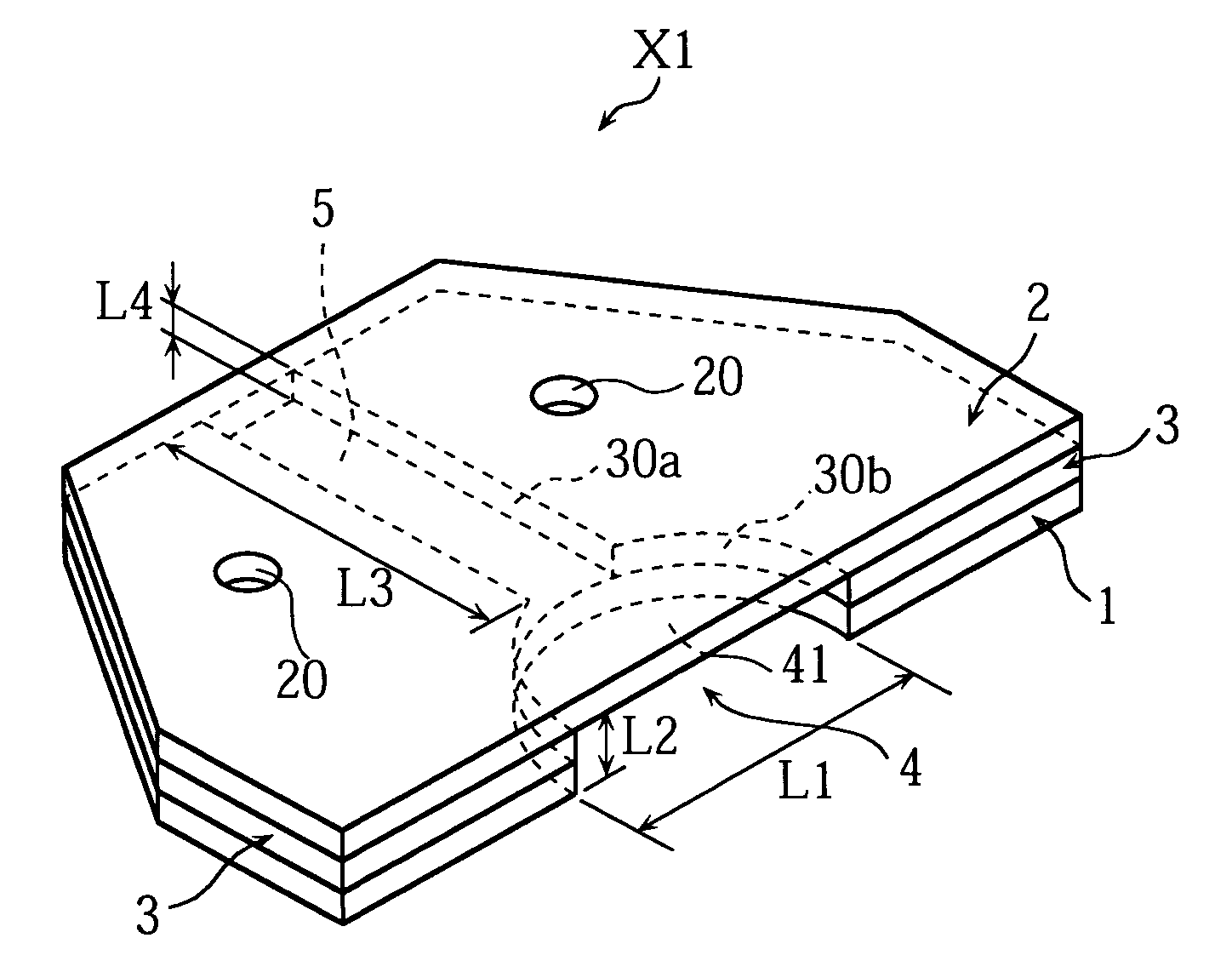
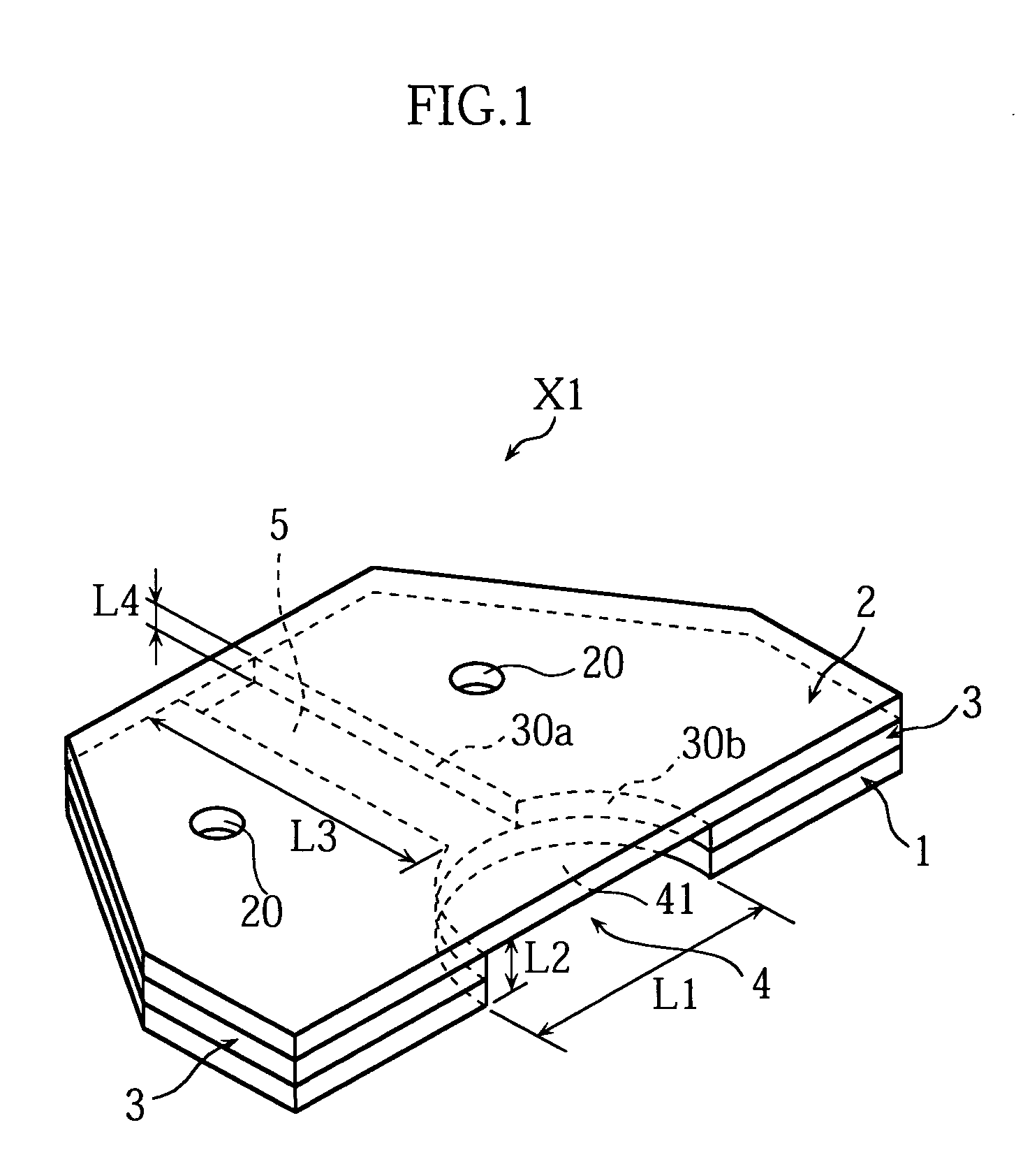
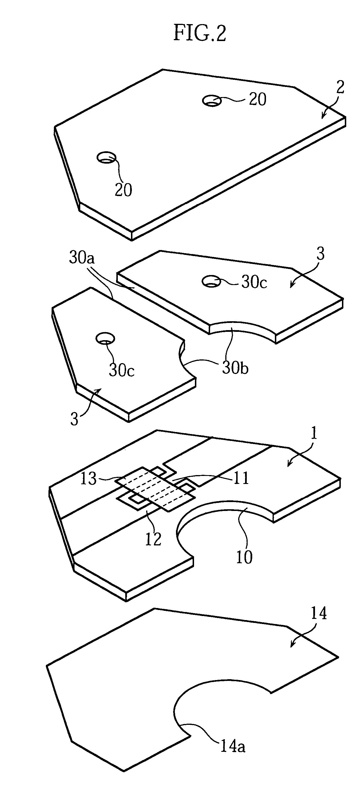
The present invention relates to an analyzing instrument (X1) provided with a capillary (5) for moving a sample liquid. The analyzing instrument (X1) includes a dehumidification region for maintaining a constant moisture content in the capillary (5). Preferably, the dehumidification region has a hygroscopicity of no less than 2%. Preferably, at least part of an inner surface of the capillary (5) extends in the moving direction of the sample liquid and is a water-insoluble high-wettability region having a wettability of no less than 57 mN / m. The dehumidification region and the high-wettability region may be made of Vinylon, for example. Preferably, the analyzing instrument (X1) includes a liquid pooling portion (4) communicating with the capillary (5) and having a portion wider than the capillary (5).

Description

TECHNICAL FIELD[0001]The present invention relates to an analyzing instrument to be mounted to a concentration measuring apparatus for measuring the concentration of a particular component in a sample liquid.BACKGROUND ART[0002]Redox reaction is generally utilized for measuring the concentration of a particular component in a body fluid, such as the concentration of glucose in blood. On the other hand, portable hand-held blood glucose level measuring apparatuses are available so that diabetics can easily measure the blood glucose level at home or away from home. For measuring the blood glucose level using such a portable blood glucose level measuring apparatus, a disposable biosensor for providing an enzyme reaction system is mounted to the blood glucose level measuring apparatus, and blood is supplied to the biosensor. Recently, to reduce the burden on the diabetics, a blood glucose level measuring apparatus integrated with a lancet has been developed so that lancing of the skin wi...

Claims


Application Information

Patent Timeline
IPC IPC(8): G01N15/06A61B5/00A61B5/15B01L3/00G01N33/487
CPCA61B5/1411A61B5/14532A61B5/1486B01L3/5027B01L2300/0645B01L2300/0809B01L2300/0825B01L2300/0887B01L2300/10B01L2400/0406G01N27/3272A61B5/150022A61B5/150099A61B5/150221A61B5/150358A61B5/15117A61B5/15123A61B5/1519A61B5/15194A61B5/157
Inventor KATSUKI, KOJISAKATA, TETSUYASHIRAKI, YASUNORI
Owner ARKRAY INC
Learn More