
Apparatuses for electrochemical deposition, conductive layer, and fabrication methods thereof

a technology of electrochemical deposition and apparatus, applied in the direction of electrolysis components, layered products, transportation and packaging, etc., can solve the problems of uneven plating thickness, high resistance deviation performance, and exacerbate abnormal process performance, so as to improve process performance and device reliability.

Inactive Publication Date: 2010-11-23
TAIWAN SEMICON MFG CO LTD
View PDF11 Cites 42 Cited by
  • Summary
  • Abstract
  • Description
  • Claims
  • Application Information

AI Technical Summary

Benefits of technology

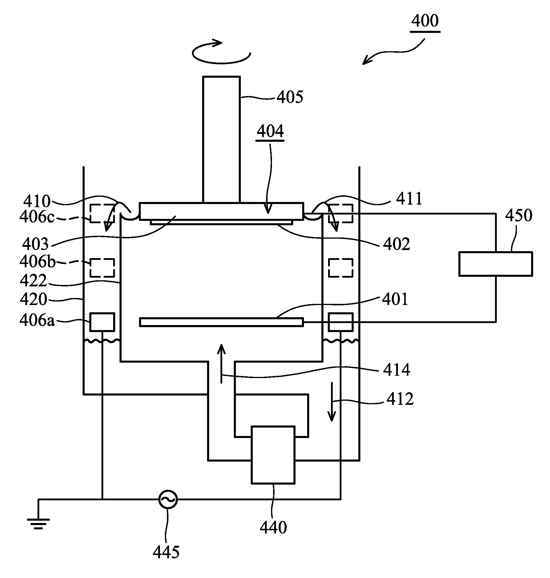
The invention provides an electrochemical deposition apparatus with an auxiliary cathode to create uniform electric flux density at both the center and circumference of a semiconductor wafer, improving process performance and device reliability. The apparatus includes a main cathode and an anode in an electrolyte bath for electrochemical deposition of a metal on the wafer. The auxiliary cathode is placed outside the electrochemical cell to provide an auxiliary electrical field such that the flux line density at the center region of the substrate holder assembly is equal to that at the circumference. The invention also provides a conductive layer on a semiconductor wafer with a seed layer over features and a conductive layer electrochemically deposited on the semiconductor wafer by the ECP apparatus with an auxiliary cathode. The deviation of mean grain size and thickness of the conductive layer between the center region and the circumference of the semiconductor wafer is less than about 3-5%. The method involves using a first multiple step function current between the anode and the main cathode and a second multiple step function current between the anode and the auxiliary cathode.

Problems solved by technology

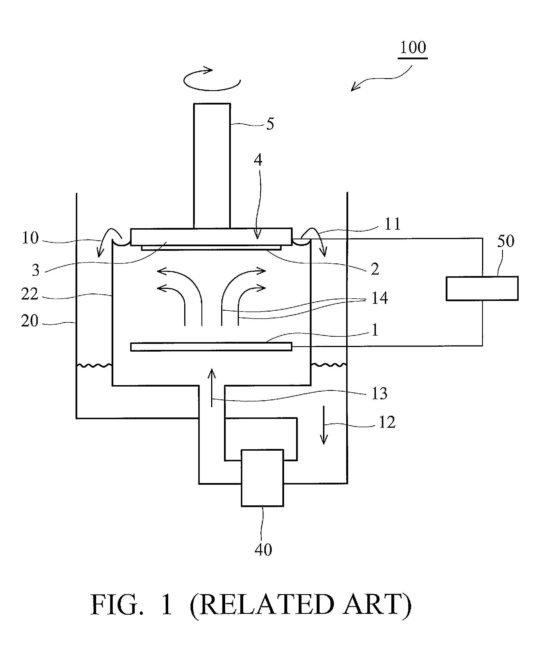
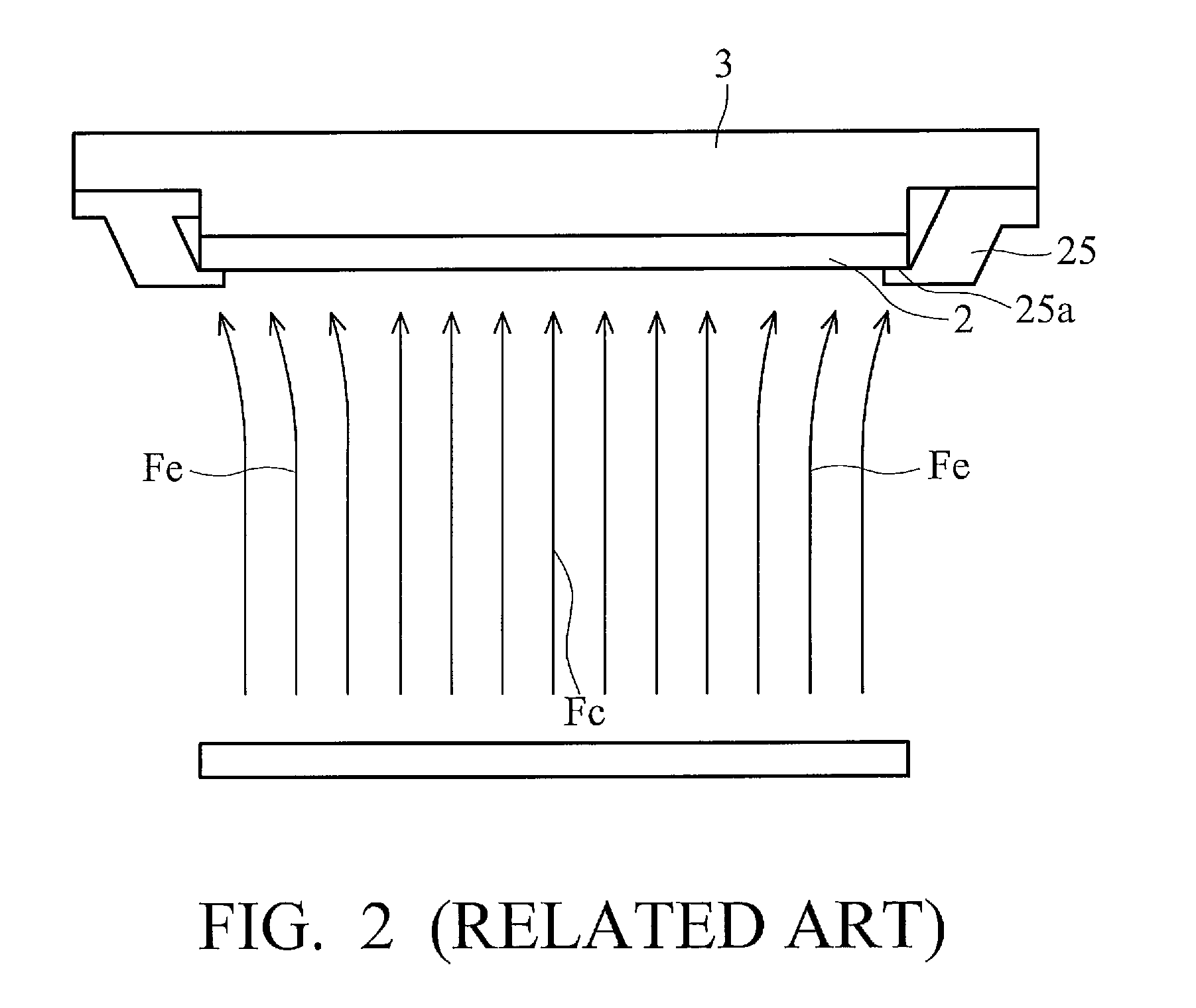
Uneven thickness can also exacerbate abnormal process performance and high resistance deviation performance.
However, it remains difficult to eliminate all edge residue and uneven plating thickness during ECD.

Method used


Image

  • Apparatuses for electrochemical deposition, conductive layer, and fabrication methods thereof
  • Apparatuses for electrochemical deposition, conductive layer, and fabrication methods thereof
  • Apparatuses for electrochemical deposition, conductive layer, and fabrication methods thereof

Examples


Embodiment Construction

[0024]The following description is of the best-contemplated mode of carrying out the invention. This description is made for the purpose of illustrating the general principles of the invention and should not be taken in a limiting sense. The scope of the invention is best determined by reference to the appended claims.

[0025]FIG. 3 is an upper plan view of an exemplarily embodiment of the ECD system 300 of the invention. Referring to FIG. 3, the ECD system 300 includes a loadlock station 310, a rapid thermal annealing (RTA) chamber 360, spin-rinse-dry (SRD) and edge bevel removal (EBR) chambers 340, a dual blade robot 380, and one or more electrochemical plating process cells 320. An electrolyte solution system (not shown) is positioned adjacent to the ECD system 300 and is individually connected to the process cells 320 to circulate electrolyte solution for the electroplating process. The ECD system 300 also includes a controller having a programmable microprocessor. A semiconductor...


PUM

PropertyMeasurementUnit
currentaaaaaaaaaa
temperatureaaaaaaaaaa
grain size distributionaaaaaaaaaa

Abstract

Electrochemical plating (ECP) apparatuses with auxiliary cathodes to create uniform electric flux density. An ECP apparatus for electrochemical deposition includes an electrochemical cell with an electrolyte bath for electrochemically depositing a metal on a substrate. A main cathode and an anode are disposed in the electrolyte bath to provide a main electrical field. A substrate holder assembly holds a semiconductor wafer connecting the cathode. An auxiliary cathode is disposed outside the electrochemical cell to provide an auxiliary electrical field such that a flux line density at the center region of the substrate holder assembly substantially equals that at the circumference of the substrate holder assembly.

Description

BACKGROUND OF THE INVENTION[0001]1. Field of the Invention[0002]The invention relates to an apparatus and method for fabricating a metal layer on a substrate, and more particularly, to an apparatus for electrochemical deposition with auxiliary cathode, conductive layer on a semiconductor wafer and a fabrication method for the same.[0003]2. Description of the Related Art[0004]Conductive interconnections on integrated circuits conventionally take the form of trenches and vias. In deep submicron integrated circuits, the trenches and vias are typically formed by a damascene or dual damascene process. Copper is currently used in ultra large scale integration (ULSI) metallization as a replacement for aluminum due to lower resistivity and better electromigration resistance. Electrochemical copper deposition (ECD) has been adopted as the standard damascene or dual damascene process because of larger grain size (good electromigration) and higher deposition rates. More particularly, electropl...

Claims


Application Information

Patent Timeline
Patent Type & Authority Patents(United States)
IPC IPC(8): C25D5/00C25D5/18C25B15/00C25D17/00
CPCH01L21/2885H01L21/76843H01L21/76864C25D17/007C25D17/001H01L21/76877Y10T428/16
Inventor CHEN, KEI-WEICHENG, MU-HANTSAI, JIAN-SINWANG, YING-LANG
Owner TAIWAN SEMICON MFG CO LTD
Learn More