Semiconductor device

a technology of semiconductors and devices, applied in the direction of liquid/fluent solid measurement, multi-programming arrangement, instruments, etc., can solve the problems of increasing the power consumption of data buses, and achieve the effects of low cost, less power consumption, and high arithmetic performan

Inactive Publication Date: 2010-11-23
SEMICON ENERGY LAB CO LTD
View PDF26 Cites 109 Cited by
  • Summary
  • Abstract
  • Description
  • Claims
  • Application Information

AI Technical Summary

Benefits of technology

[0008]Data transmission from each CPU to the router circuit is carried out through modulation of a wireless signal. Modulation such as phase modulation or amplitude modulation is achieved by turning on or off a switch of a wireless circuit included in each CPU. With the use of such a modulation method, i.e., a backscattering method, the amount of power needed for data transmission from each CPU can be reduced.
[0014]The present invention can provide a multi-core semiconductor device which consumes less power and has high arithmetic performance, at low cost. By providing a plurality of CPUs, a router circuit, and a thread control circuit and employing a backscattering method for data transmission from each CPU to the router circuit, the present invention can also provide a semiconductor device which can transmit data from each CPU to the router circuit while consuming a very small amount of power. The present invention can further provide a semiconductor device having a lot of flexibility in physical form because the CPU does not need to be electrically connected to another CPU, the router circuit, the thread control circuit, and an external terminal.

Problems solved by technology

However, even if the multi-core system is employed, since data transmission and reception between CPUs or the like become necessary, an increase in the amount of power consumed by a data bus for them becomes a problem.

Method used


Image

  • Semiconductor device
  • Semiconductor device
  • Semiconductor device

Examples


embodiment mode 1

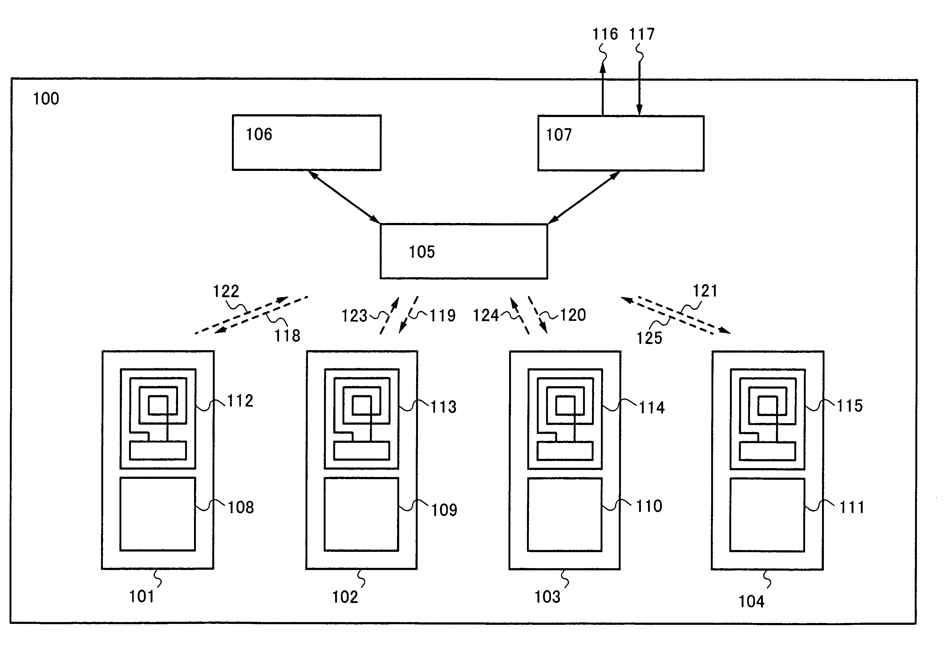
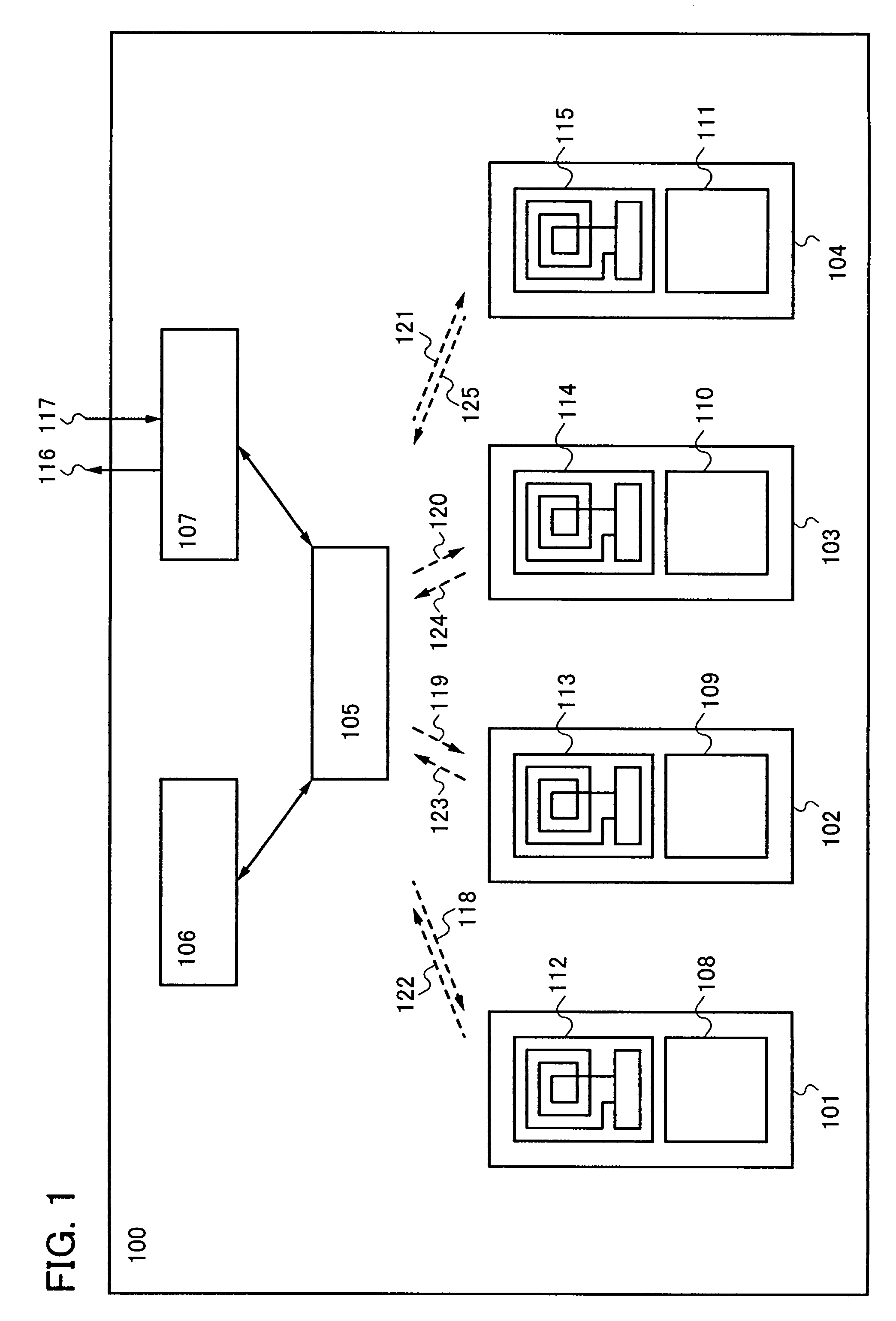
[0034]Embodiment Mode 1 describes an example of a structure of a semiconductor device of the present invention with reference to FIGS. 1 to 3. FIGS. 1 to 3 are block diagrams of a semiconductor device, a CPU, and a router circuit of this embodiment mode, respectively.

[0035]In FIG. 1, a semiconductor device 100 has first to fourth CPUs 101 to 104, a router circuit 105, a thread control circuit 106, and an external device controller 107. The first to fourth CPUs 101 to 104 have first to fourth CPU cores 108 to 111 and first to fourth wireless circuits 112 to 115, respectively. Note that in FIG. 1, the router circuit 105 transmits first to fourth wireless transmission signals 118 to 121 to the first to fourth CPUs 101 to 104, and the first to fourth CPUs 101 to 104 transmit fifth to eighth wireless transmission signals 122 to 125 to the router circuit 105, respectively. The semiconductor device 100 transmits and receives a data signal or a control signal to and from an external device ...

embodiment mode 2

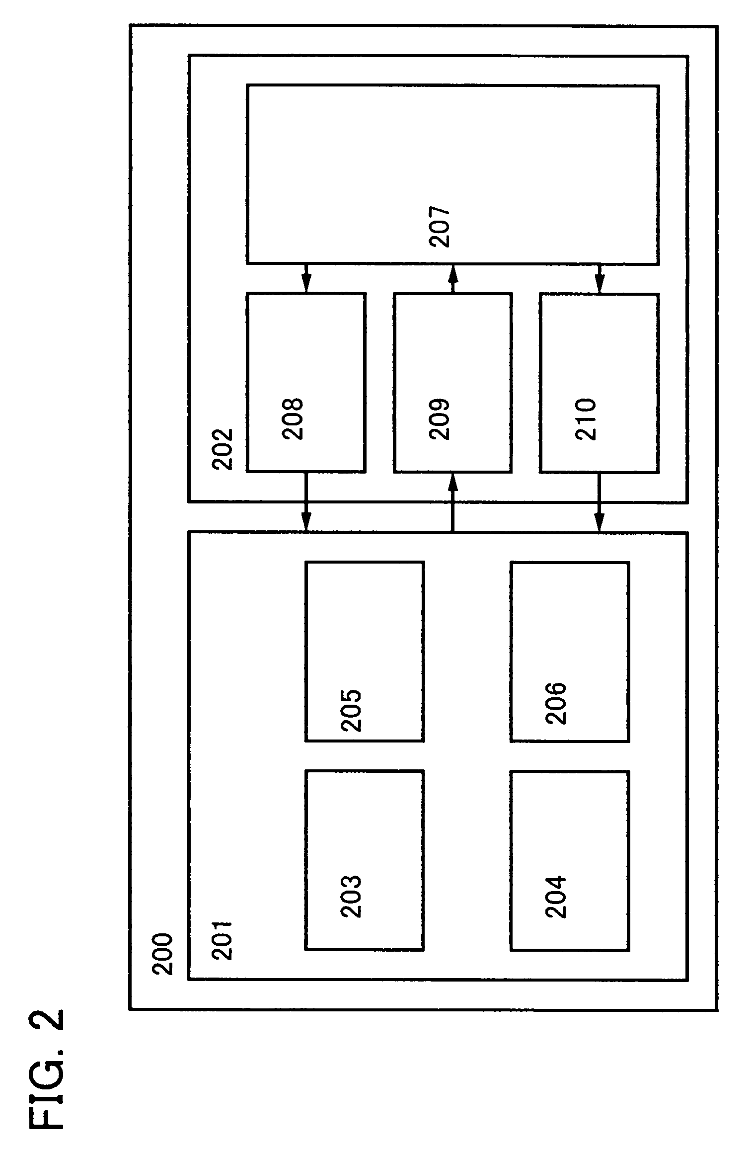
[0053]Embodiment Mode 2 describes the structure of the wireless circuit of the CPU in the above embodiment mode with reference to FIG. 4. FIG. 4 shows a case where the wireless circuit has the antenna circuit 207, the demodulation circuit 208, the modulation circuit 209, and the power supply circuit 210.

[0054]In FIG. 4, the modulation circuit 209 has a transistor 406 and can superimpose transmission data on a communication signal by changing the potential of a modulation signal line 402.

[0055]The demodulation circuit 208 has a first coupling capacitor 407, a first diode 408, a second diode 409, an LPF resistor 410, and an LPF capacitor 411. A first AC voltage obtained from a communication signal by the antenna circuit 207 is supplied through a wiring 401 and converted into a second AC voltage by the first coupling capacitor 407, and the second AC voltage is supplied to a wiring 412. The second AC voltage is converted into a DC voltage by a rectifier circuit which has the first diode...

embodiment mode 3

[0059]Embodiment Mode 3 describes a structure of a wireless circuit of a CPU, which is different from that of Embodiment Mode 2, with reference to FIG. 5.

[0060]In FIG. 5, the antenna circuit 207 has a first antenna 534 and a second antenna 535. The first antenna 534 is used for data transmission and reception with a first communication signal and for generation of a first power supply voltage from the first communication signal. The second antenna 535 is used for generation of a second power supply voltage from a second communication signal.

[0061]The modulation circuit 209 has a transistor 506 and can superimpose transmission data on the first communication signal by changing the potential of a modulation signal line 502.

[0062]The demodulation circuit 208 has a first coupling capacitor 507, a first diode 508, a second diode 509, an LPF resistor 510, and an LPF capacitor 511. A first AC voltage obtained from the first communication signal by the first antenna 534 is supplied through ...


PUM


Abstract

In a multi-core semiconductor device, a data bus between CPUs or the like consumes a larger amount of power. By provision of a plurality of CPUs which transmit data by a backscattering method of a wireless signal, a router circuit which mediates data transmission and reception between the CPUs or the like, and a thread control circuit which has a thread scheduling function, a semiconductor device which consumes less power and has high arithmetic performance can be provided at low cost.

Description

TECHNICAL FIELD[0001]The present invention relates to a semiconductor device having a plurality of CPUs, which is called a multi-core semiconductor device.BACKGROUND ART[0002]Currently, almost all central processing units (CPUs) included in semiconductor devices adopt an architecture called a stored-program system. In this stored-program system, instructions to be processed by a CPU and data necessary for the processing are stored in a memory, and the CPU performs processing by sequentially reading data from the memory. Therefore, for the semiconductor device having a CPU, techniques for increasing an operating frequency of CPU and increasing a memory access rate are employed in order to improve performance.[0003]The semiconductor device can have higher arithmetic processing performance by increasing the operating frequency of the CPU. However, the amount of electric power consumed by the semiconductor device is increased in proportion to the operating frequency. In addition, an inc...

Claims


Application Information

Patent Timeline
Patent Type & Authority Patents(United States)
IPC IPC(8): H04B1/38
CPCG06F15/7832H04B5/0037Y02B60/1225Y02B60/1207Y02D10/00G06F1/32G06F9/46G06F12/00
Inventor KUROKAWA, YOSHIYUKI
Owner SEMICON ENERGY LAB CO LTD
Why Eureka
Try Eureka